Supplied By www.heating spares.co Tel. 0161 620 6677
GAS CONTROL VALVE
INCLUDING AIR INLET COWL
9.3
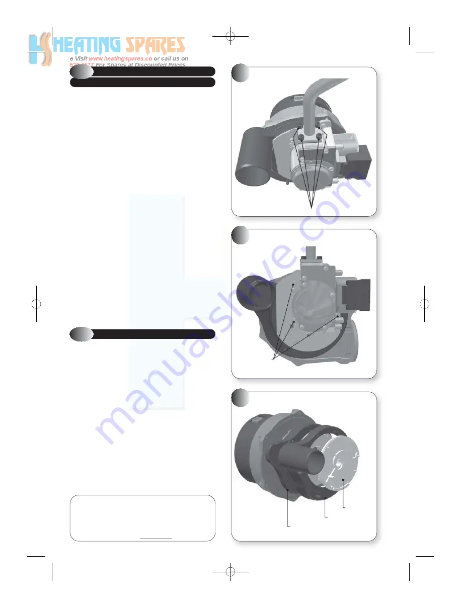
Refer to Figures 33, 34 & 35
a)
Ensure supply voltage is isolated, and that the gas supply is isolated.
b)
Remove the gas control valve, fan & burner assembly; refer to
section 6.2.
c)
Unscrew four screws holding the gas feed pipe, and remove gas feed
pipe, refer to Figure 33.
Note: Newer versions may have a single flange nut securing the gas
feed pipe.
d)
Unscrew three torx screws (T-20), and remove gas control valve,
refer to Figure 34
e)
Unclip the top section of the black plastic air inlet cowl from the fan
assembly, and remove white plastic insert, clean or replace as
necessary, refer to Figure 35.
f)
Refit or replace the top section of the black plastic air inlet cowl,
ensuring that it is clipped into place and that the holes in the white
plastic insert are aligned with the fixing holes.
g)
Attach and secure the gas feed pipe to the replacement gas valve,
using a new gasket.
h)
Attach and secure the replacement gas control valve to the fan
assembly.
i)
Re-assemble in reverse order; ensure that all joints and seals are
correctly re-fitted.
Note:
The gas control valve is factory set and sealed and is not
adjustable. If the gas control valve is changed, then when the appliance
is running, the flue gas CO
2
should be measured, refer to section 6.1,
and compared to the values stated in Performance Data, section 2.2. If
the measured value does not correspond to the Performance Data, then
contact: Halstead Boilers Ltd. Service Help line: 0844 371 1111.
COMBUSTION CHECK SET-UP
9.3.2
When installing, commissioning or servicing a gas
appliance that incorporates a pre-mix burner and zero-
set governor, because it is not possible to measure an
operating pressure the engineer should first check that
the gas supply is metered and ascertain whether it is possible to
measure the gas rate. If the gas input rate can be measured then the
requirements of GSIUR 26(9) can be met, including any specific
requirements in manufacturers’ instructions.
If gas input rate cannot be measured then, to satisfy the intent of
GSIUR 26(9), the engineer shall measure the combustion quality of the
appliance in accordance with BS 7967 or the manufacturers’
instructions.
If the engineer does not have the required equipment and no
alternative test is specified by the manufacturer then the appliance
shall be turned off and disconnected as an un-commissioned appliance
until such time that equipment is available to undertake such tests.
If a new gas valve is fitted it must be adjusted as per the instructions
that are supplied with the new gas valve.
A suitable, calibrated flue gas analyser is required to measure the CO
2
.
!
33
GAS FEED PIPE CONNECTION TO GAS
CONTROL VALVE
35
AIR INLET COWL
34
GAS CONTROL VALVE
4 SCREWS
3 TORX
SCREWS
SWIRL PLATE
AIR INLET COWL TOP
AIR INLET COWL BOTTOM
33
IMPORTANT:
After any adjustment of the gas valve,
it is essential to check the combustion levels at
minimum gas rate (table 2.3). If the Carbon Monoxide
or Carbon Dioxide levels are outside the range
quoted, call Halstead Boilers Ltd Technical Helpline
on 0844 371 1111.
If in doubt ASK!
!
751030 MANUAL (NEW) 21/9/10 08:42 Page 27


