


4
4
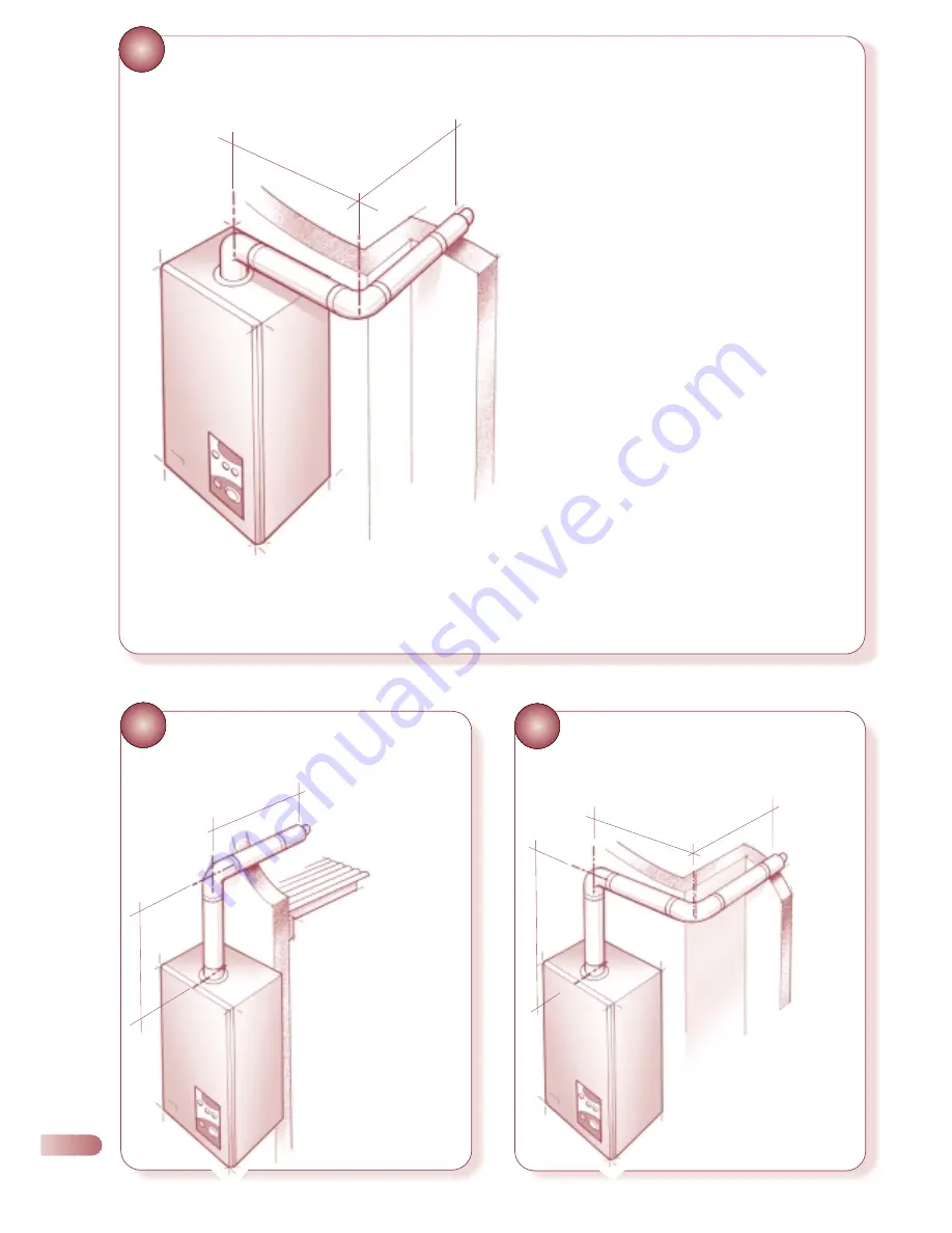
SPECIFICATION FOR FLUE SYSTEMS
WITH AN EXTRA 90° ELBOW
a
b
Fig 4 - Use of the flanged elbow, extension(s), 90°
extension elbow, and standard flue assembly.
Maximum allowable flue length of ‘a’ + ‘b’ = Ace 3233mm,
Ace High 1233mm.
(i.e maximum horizontal flue lengths minus resistive length of
767mm for 90° extension elbow.)
5
SPECIFICATION FOR FLUE SYSTEMS
WITH AN ELEVATED FLUE SYSTEM
6
SPECIFICATION FOR FLUE SYSTEMS
WITH AN ELEVATED FLUE SYSTEM
INCORPORATING BENDS
•
•
b
a
•
•
•
•
•
•
•
b
a
c
Fig 5 - Use the vertical turret
socket, 90° extension elbow,
standard flue assy &
extension(s)
‘a’ measured from the top of the
boiler casing to the centre line of the
extension elbow.
‘b’ measured from the centre line of
the extension elbow to the outside
wall face .
Maximum allowable flue length of
‘a’ + ‘b’ = Ace 4000mm, Ace High
2000mm.
Fig 6 - As fig. 5 but with
additional 90° extension elbow.
‘a’measured from the top of the boiler
casing to the centre line of the extension
elbow
‘b’ measured from the centre line of the
extension elbow to the centre line of the
second extension elbow
‘c’ measured from the centre line of the
second extension elbow to the outside wall
face.
Maximum allowable flue length of
‘a’ + ‘b’ + ‘c’= Ace 3233mm, Ace High
1233mm.
•
•
•
Summary of Contents for Ace High
Page 8: ...8 EXPLODED DIAGRAM for key no references see spare parts catalogue Drawing amended 8 6 00 6 ...
Page 25: ...INTERNAL WIRING DIAGRAMS 7 7 1 FUNCTIONAL FLOW WIRING DIAGRAM 23 ...
Page 26: ...7 2 ILLUSTRATED WIRING DIAGRAM 24 ...
Page 40: ...Ace Ace High Wickes Combi 82 102 05 04 ACE ACE HIGH WICKES COMBI 82 102 ...