SENSITRON
A Halma Company
MT4984
MU+ PK-32
Manual (EN)
P. 52/14
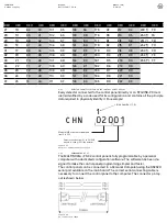
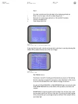
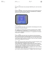
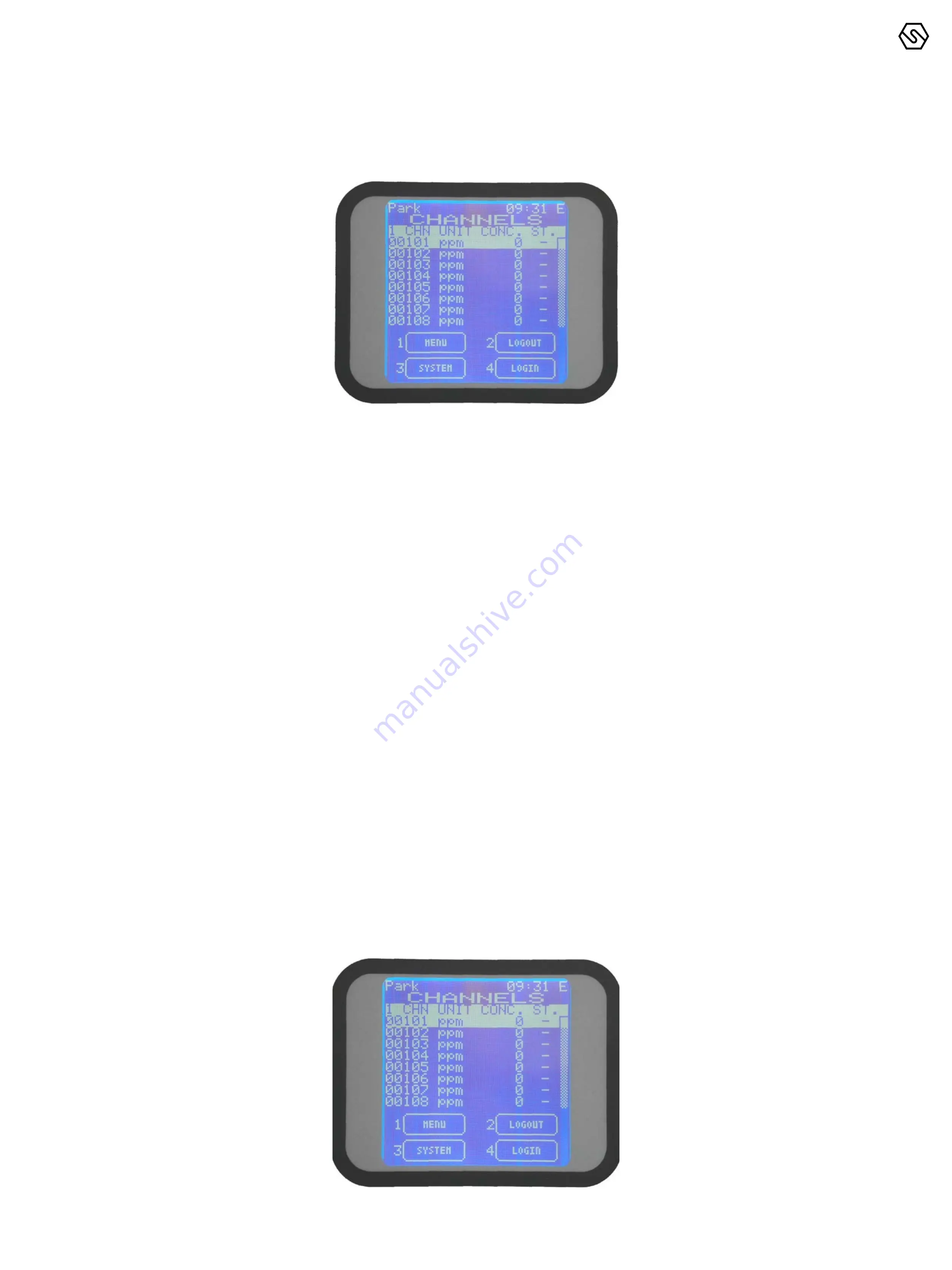
For an already configured control panel, the normal screen will show eight chan-
nels (detectors) with their status:
3.2
SYSTEM STATES AND OPERATION
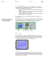
The LCD display provides the user with details about the various system states.
A few general rules apply at any level as follows:
-
Should there be a list displayed, the page scrolling can be done using
the UP/DOWN arrow keys. Once a selection is made by pressing the
ENTER key the display will show a more detailed view of that particular
selection.
-
All the arrow keys, UP/DOWN, LEFT/RIGHT are being used also to
move through the parameter under change fields.
-
At any display level, the ESC key will switch back to the previous view.
Pressing twice the ESC key, you will go back to the main screen.
-
The same, at any display level, should no keys be pressed for more
that 3 minutes, the view will automatically switch back to the main
window of the Normal mode.
3.3
SYSTEM STATES
The system is designed to be in one of the following operative states:
NORMAL, ALARM, FAULT, TEST/MAINTENANCE, UNSET, EMERGENCY
-
Normal
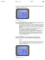
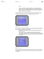
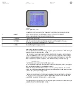
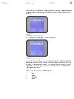
It is the normal system operative state without alarms and faults. The
screen in this state displays the channels (gas detectors) with meas-
ured gas concentration.
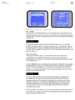
Figure 19
Typical NORMAL state screen.
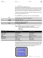
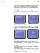
Figure 20
Typical NORMAL state screen.

