SENSITRON
A Halma Company
MT4984
MU+ PK-32
Manual (EN)
P. 43/14
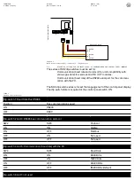
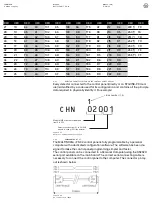
Dip-switch 8: restore default settings
Position
Function
ON
If set to ON, default data is restored when the gas control unit is switched on
and the configuration is deleted
OFF
Normal position
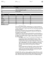
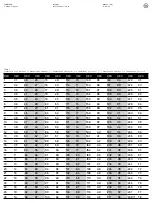
Language
SW4
SW3
SW2
SW1
English
ON
OFF
OFF
OFF
Italian
ON
ON
ON
OFF
Spanish
ON
ON
OFF
ON
Portuguese
ON
ON
OFF
OFF
German
ON
OFF
ON
ON
French
ON
OFF
ON
OFF
Slovenian
ON
OFF
OFF
ON
Table 4
SD3 dip switch series settings
2.7
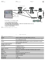
FIELD DEVICE CONNECTIONS
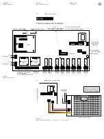
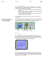
The unit has as default condition 1 RS485 data bus connected to field gas de-
tectors. As option, 1 more serial line can be added.The serial buses can be used
in “open” mode (2 bus) or “closed” (1 bus). The choice is set during programming
with the PC software.
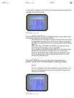
Via serial bus the gas detectors are connected (directly via RS485 serial for
Smart P model or via the 8-input STG/IN8-PK modules if 4-20 mA type) and
ST.G/OUT16-S output modules.
The length of each serial data bus is maximum 1000 mt. 4 conductors are re-
quired for device connections (meaning both Smart P detectors and IN and OUT
modules): 2 for the RS485 serial bus and two for device power. For this reason,
two different wires must be used or a single wire that has suitable characteris-
tics, described below
-
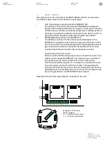
The RS485 serial bus must be connected with an EIA RS 485 connec-
tion wire: No. 2 conductors with 0.22/0.35 mm2 s shield
(TWISTED PAIR). Nominal capacity between conductors < 50 pF/m,
nominal impedance 120 ohm. Total line length with this type of con-
nection must not exceed 1.000 meters. An example of a recommended
wire is a BELDEN 9841 or similar wire (EIA RS485 data transmission
wire). Only connect detectors (and IN and OUT modules) in cascade.
Avoid tree or delta connection since they reduce interference
immunity.
-
Detector power supply (and IN and OUT modules on the bus) must be
connected with a 2-core wire with adequate section based on the
number of connected devices, their distance from the power supply
and each device’s consumption (please see the technical manual e
closed with gas detectors for this purpose).
The MU+PK-32 can support a different number of detectors up to 32.
Each device connected on the unit’s RS485 bus must have its own univocal ad-
dress. STG/IN8-PK and STG/OUT16-S module address settings are described
later in this manual. See the manual of the detector for its address settings.

