SENSITRON
A Halma Company
MT4984
MU+ PK-32
Manual (EN)
P. 50/14
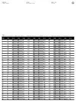
DEC
HEX
DEC
HEX
DEC
HEX
DEC
HEX
DEC
HEX
DEC
HEX
DEC
HEX
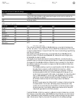
27
1B
64
40
101
65
138
8A
175
AF
212
D4
249 (*) F9
28
1C
65
41
102
66
139
8B
176
B0
213
D5
250 (*) FA
29
1D
66
42
103
67
140
8C
177
B1
214
D6
251 (*)
FB
30
1E
67
43
104
68
141
8D
178
B2
215
D7
252 (*) FC
31
1F
68
44
105
69
142
8E
179
B3
216
D8
253 (*) FD
32
20
69
45
106
6A
143
8F
180
B4
217
D9
254 (*) FE
33
21
70
46
107
6B
144
90
181
B5
218
DA
255 (**) FF
34
22
71
47
108
6C
145
91
182
B6
219
DB
35
23
72
48
109
6D
146
92
183
B7
220
DC
36
24
73
49
110
6E
147
93
184
B8
221
DD
37
25
74
4A
111
6F
148
94
185
B9
222
DE
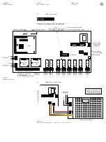
2.13
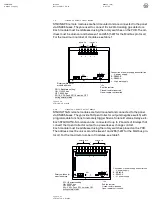
DETECTOR IDENTIFICATION ON THE CONTROL PANEL DIPLAY
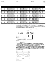
Every detector connected to the control panel (directly or on STG/IN8-PK mod-
ule) is identified by a code used for its configuration and contains all the principle
data required to physically identify it. For example:
2.14
PROGRAMMING BY PC
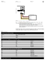
The MU+PK-32 control panel is fully programmable by a personal
computer with a dedicated configuration software. The software has been de-
signed to make the control panel programming simpler and faster.
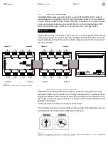
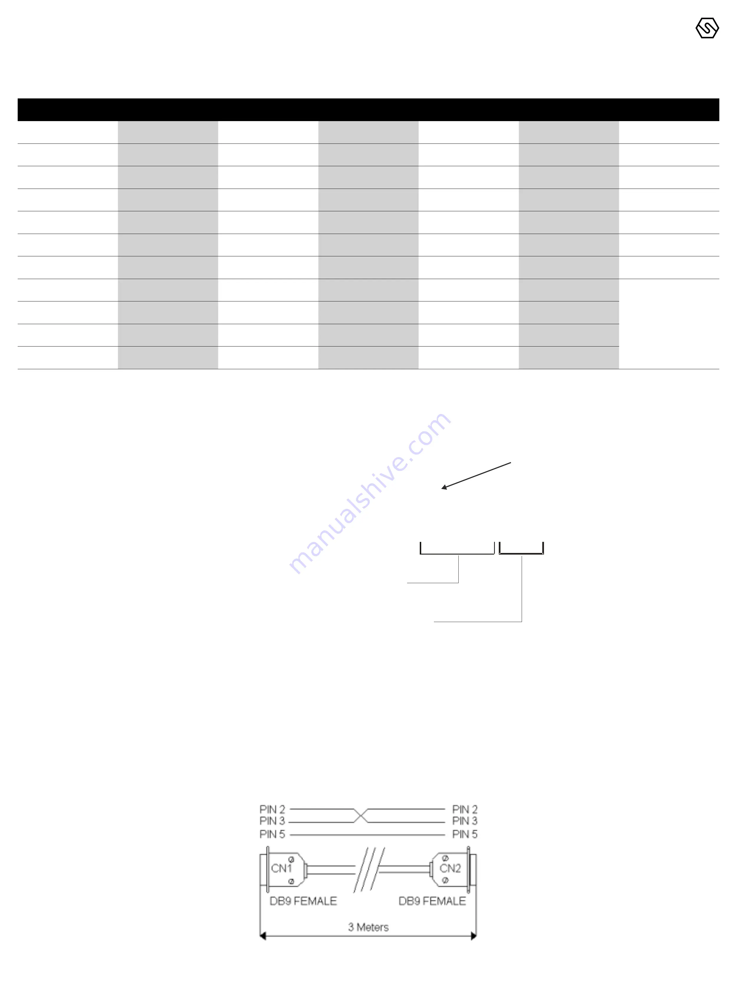
The control panel can be connected to a Personal Computer using the RS232C
serial port available on the main board. The correct serial connecting cable is
necessary to connect the control panel to the computer. The connector pin lay-
out is shown below.
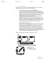
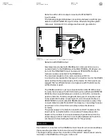
Figure 15
Detector number identification
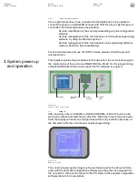
Figure 16
PC connection cable
CHN 02001
Module IN8 or detector address
from 0 to 255
Detector position from 01 to 08 if IN8
module is used or 00 if the detector
is connected on bus
1
Bus number (1-4)


