OUTDOOR UNIT CONTROLS and COMPONENTS
PAGE 8
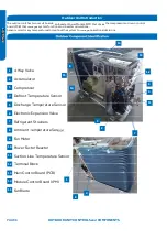
Outdoor Unit Introduction
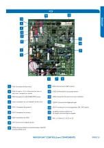
The outdoor unit has two circuit boards,
an Inverter Power Module (IPM) that
drives the compressor and main control
board (PCB) that manages system functions and inverter calculations.
Sensors monitor key temperatures throughout the system to manage operational decisions.
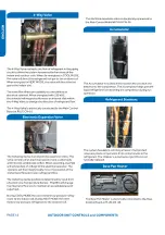
4-Way Valve
Accumulator
Compressor
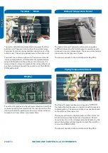
Defrost Temperature Sensor
Discharge Temperature Sensor
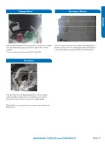
Electronic Expansion Valve
Refrigerant Strainers
Ambient Temperature Sensor
Fan Motor
Power Factor Reactor
Suction Line Temperature Sensor
Terminal Block
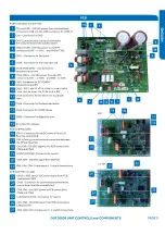
Main Control Board (PCB)
Module Control Board (IPM)
Fan Blade
1
2
3
4
5
6
7
8
9
10
11
12
13
14
15
8
4
6
11
12
13
14
1
3
2
7
5
9
10
15
Summary of Contents for AW09EH2VHD
Page 2: ... This page intentionally left blank ...
Page 4: ...Failure to follow any CAUTION may in some cases result in grave consequences ...
Page 6: ...PAGE 6 ...
Page 9: ...5VDC and 15VDC pulsing communication connection between the PCB and the IPM ...
Page 10: ......
Page 11: ......
Page 12: ......
Page 13: ......
Page 14: ......
Page 15: ...Connector for coil temperature sensor and room temperature sensor ...
Page 17: ......
Page 19: ......
Page 22: ......
Page 23: ......
Page 26: ...PAGE 32 ...
Page 50: ...Error Code E7 LED1 15 Flash Wiring Diagram Reference PAGE 50 ERROR CODES and Troubleshooting ...
Page 57: ...PAGE 57 Ambient Defrost and Pipe Sensor Tables Discharge Sensor Tables ...

