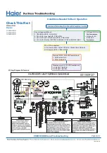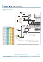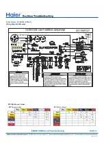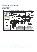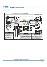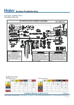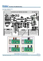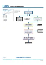
OUTDOOR UNIT WIRING DIAGRAM
●
COMPRESSOR
0011509127
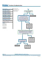
Check This First
Outoor Unit
Models:
1U09EH2VHD
1U12EH2VHD
1U18EH2VHD
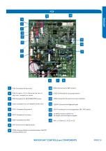
Line voltage available at:
1. TERMINAL STRIP - 1(N) & 2 (L)
2. AC-L & AC-N at the PCB - CN2 & CN1
3. AC-L OUT & AC-N OUT at the PCB - CN8 & CN9
4. AC-L & AC-N at the IPM -CN8 & CN9 (9K) / CN1 & CN2 (12K/18K)
310+ VDC available at:
1. P & N at the IPM - CN1 & CN5 (9K) / CN8 & CN9 (12K/18K)
2. P & N at the PCB - CN24 & CN26
Module COM 5-G-15 VDC available at:
1. CN23 at the PCB
2. CN11 at the IPM
Module power 5-G-15 VDC available at:
1. CN22 AT THE PCB
2. CN10 AT THE IPM
• 1 (N) and 3 (C): 0-80
• 2 (L) and 3 (C):
0-140 VAC
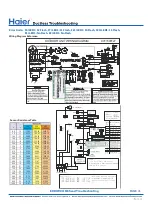
Wiring Diagram Reference
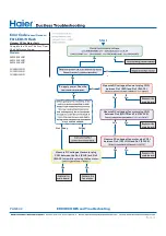
Conditions Needed for Basic Operation
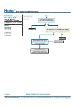
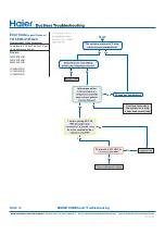
ERROR CODES and Troubleshooting
●
PAGE 29
Summary of Contents for AW09EH2VHD
Page 2: ... This page intentionally left blank ...
Page 4: ...Failure to follow any CAUTION may in some cases result in grave consequences ...
Page 6: ...PAGE 6 ...
Page 9: ...5VDC and 15VDC pulsing communication connection between the PCB and the IPM ...
Page 10: ......
Page 11: ......
Page 12: ......
Page 13: ......
Page 14: ......
Page 15: ...Connector for coil temperature sensor and room temperature sensor ...
Page 17: ......
Page 19: ......
Page 22: ......
Page 23: ......
Page 26: ...PAGE 32 ...
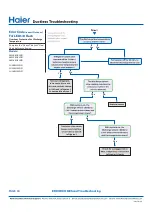
Page 50: ...Error Code E7 LED1 15 Flash Wiring Diagram Reference PAGE 50 ERROR CODES and Troubleshooting ...
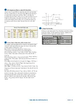
Page 57: ...PAGE 57 Ambient Defrost and Pipe Sensor Tables Discharge Sensor Tables ...

