OUTDOOR UNIT CONTROLS and COMPONENTS
PAGE 7
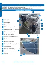
Outdoor Unit Controls and Components
Table of Contents
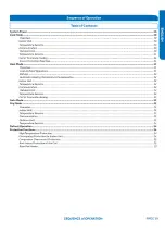
Outdoor Unit Introduction ................................................................................................................................................. 8
8
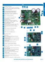
Outdoor Main Control Boa
●
rd .............................................................................................................................................. 9
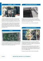
Terminal Block .................................................................................................................................................................. 10
Reactor ............................................................................................................................................................................ 10
Compressor ..................................................................................................................................................................... 10
Outdoor Fan Motor ........................................................................................................................................................... 10
Discharge Temperature Sensor ........................................................................................................................................ 11
Defrost Temperature Sensor ............................................................................................................................................ 11
Outdoor Ambient Temperature Sensor ............................................................................................................................ 11
Suction Line Temperature Sensor ..................................................................................................................................... 11
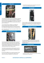
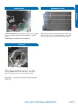
4-Way Valve ..................................................................................................................................................................... 12
Electronic Expansion Valve ............................................................................................................................................... 12
Accumulator ...................................................................................................................................................................
●
. 12
Strainers
......................................................................................................................... ................................................ 12
Base Pan Heater............................................................................................................................................................... 12
....................................................................................................................................
Summary of Contents for AW09EH2VHD
Page 2: ... This page intentionally left blank ...
Page 4: ...Failure to follow any CAUTION may in some cases result in grave consequences ...
Page 6: ...PAGE 6 ...
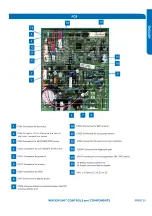
Page 9: ...5VDC and 15VDC pulsing communication connection between the PCB and the IPM ...
Page 10: ......
Page 11: ......
Page 12: ......
Page 13: ......
Page 14: ......
Page 15: ...Connector for coil temperature sensor and room temperature sensor ...
Page 17: ......
Page 19: ......
Page 22: ......
Page 23: ......
Page 26: ...PAGE 32 ...
Page 50: ...Error Code E7 LED1 15 Flash Wiring Diagram Reference PAGE 50 ERROR CODES and Troubleshooting ...
Page 57: ...PAGE 57 Ambient Defrost and Pipe Sensor Tables Discharge Sensor Tables ...

