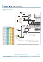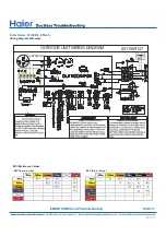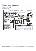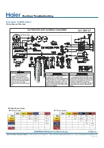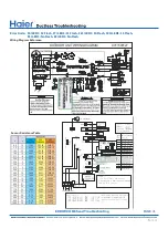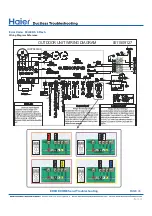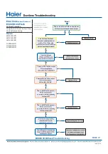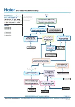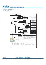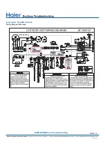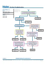
See reverse side for
●
wiring diagram, relevant
●
color-coded test
positions, and sensor
resistance values.
Error Codes
(Indoor/Outdoor)
F6/LED1: 12 Flash
Ambient Temperature Sensor Failure
F7/LED1: 11 Flash
Suction Temperature Sensor Failure
F21/LED1: 10 Flash
Defrost Temperature Sensor Failure
F25/LED1: 13 Flash
Discharge Temperature Sensor Failure
●
E1/LED1: No Flash
Room Temperature Sensor Failure
E2/LED1: No Flash
Indoor Coil Temperature Sensor Failure
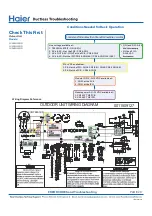
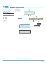
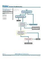
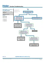
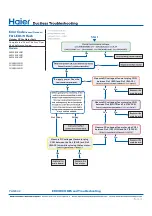
Complete the “Check This First” Flow
Chart before continuing.
Models:
AW09EH2VHD
AW12EH2VHD
AW18EH2VHD
1U09EH2VHD
1U12EH2VHD
1U18EH2VHD
Yes
Yes
Yes
Yes
No
No
No
No
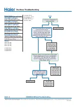
Go to next step
to test the board
as well before
sensor as well if
previous step.
Re-seat and
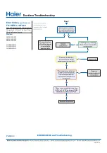
Start
wires for the faulting sensor. Does
(See Reverse side.)
solder joints or through the top of the Molex
Is the temperature at the
sensor out of operating
PAGE 40
●
ERROR CODES and Troubleshooting
Summary of Contents for AW09EH2VHD
Page 2: ... This page intentionally left blank ...
Page 4: ...Failure to follow any CAUTION may in some cases result in grave consequences ...
Page 6: ...PAGE 6 ...
Page 9: ...5VDC and 15VDC pulsing communication connection between the PCB and the IPM ...
Page 10: ......
Page 11: ......
Page 12: ......
Page 13: ......
Page 14: ......
Page 15: ...Connector for coil temperature sensor and room temperature sensor ...
Page 17: ......
Page 19: ......
Page 22: ......
Page 23: ......
Page 26: ...PAGE 32 ...
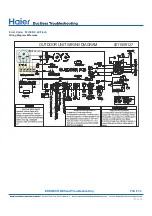
Page 50: ...Error Code E7 LED1 15 Flash Wiring Diagram Reference PAGE 50 ERROR CODES and Troubleshooting ...
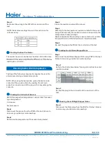
Page 57: ...PAGE 57 Ambient Defrost and Pipe Sensor Tables Discharge Sensor Tables ...

