PAGE 27
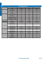
SYSTEM SPECIFICATIONS
System
System
EH*
EH*
EH*
Outdoor
1U09EH2VHD
1U12EH2VHD
1U18EH2VHD
Indoor
AW09EH2VHD
AW12EH2VHD
AW18EH2VHD
Rated Capacity
Btu/hr
9,000
12,000
18,000
Capacity Range
Btu/hr
3100~12000
3100~15000
8,500~21000
Rated Power Input
W
560
800
1,385
SEER
30
27
23
EER
16.0
15.0
13.0
M oisture Removal
Pt./h
0.60
1.60
3.80
Rated Heating Capacity 47°F
Btu/hr
10,000
14,500
20,000
Heating Capacity Range
Btu/hr
3100~20000
3100~22000
8700-27000
Rated Power Input
W
845
1,400
1,920
HSPF
15.2
13.0
12.0
M ax. Heating Capacity 5°F
Btu/hr
12,000
17,000
25,000
M ax. Heating Capacity -4°F
Btu/hr
10,500
15,500
22,000
M ax. Hea
●
ting Capacity -15°F
Btu/hr
8,600
14,500
20,000
M ax. Heating Capacity -22°F
Btu/hr
7,400
12,400
17,200
M ax. Heating Capacity -31°F
Btu/hr
3,200
5,400
7,400
C
●
ooling
°F(°C)
14~115(-10~46)
14~115(-10~46)
14~115(-10~46)
Heating
°F(°C)
-31~75(-35~24)
-31~75(-35~24)
-31~75(-35~24)
Power Supply
Voltage, Cycle, Phase
V/Hz/-
208-230/60/1
208-230/60/1
208-230/60/1
Compressor Type
DC Inverter Rotary
DC Inverter Rotary
DC Inverter Rotary
M aximum Fuse Size
A
15
20
30
M inimum Circuit Amp
A
13
14
20
Outdoor Noise Level
dB
55
55
51
Dimension: Height
in (mm)
27 1/2(697)
27 1/2(697)
30(762)
Dimension: Width
in (mm)
35(890)
35(890)
36 1/4(920)
Dimension: Depth
in (mm)
13 7/8(353)
13 7/8(353)
15 1/8(385)
Weight (Ship/Net)-
lbs (kg)
119.7/102.198.3 (54.3/46.3)
124.6/108 (56.5/49)
152.6/132.7 (69.2/60.2)
Fan Speed Stages
5 + Auto
5 + Auto
5 + Auto
Indoor Sound Level dB
(Turbo/High/M ed/Low/Quiet)
48/38/35/32/28
48/46/39/32/30
49/46/41/36/32
Dimension: Height
in (mm)
12 7/8 (327)
12 7/8 (327)
13 1/4 (337)
Dime
●
nsion: Width
in (mm)
39 3/4 (1009)
39 3/4 (1009)
44 3/8 (1126)
Dimension: Depth
in (mm)
8 3/4 (223)
8 3/4 (223)
9 1/16 (230)
Weight (Ship/Net)-
lbs (kg)
36.4/28.7 (16.5/13)
36.4/28.7 (16.5/13)
44.1/37.5 (20/17)
Connections
Flare
Flare
Flare
Liquid O.D.
in
1/4
1/4
1/4
Suction O.D.
in
1/2
1/2
1/2
Factory Charge
Oz
57.0
62.1
82.9
M aximum Line Length
Ft / m
50/15
50/15
83/25
M aximum Height
Ft / m
33/10
33/10
50/15
M odel Name
Refrigerant Line
Cooling
Operating Range
Outdoor Unit
Indoor Unit
Heating
Summary of Contents for AW09EH2VHD
Page 2: ... This page intentionally left blank ...
Page 4: ...Failure to follow any CAUTION may in some cases result in grave consequences ...
Page 6: ...PAGE 6 ...
Page 9: ...5VDC and 15VDC pulsing communication connection between the PCB and the IPM ...
Page 10: ......
Page 11: ......
Page 12: ......
Page 13: ......
Page 14: ......
Page 15: ...Connector for coil temperature sensor and room temperature sensor ...
Page 17: ......
Page 19: ......
Page 22: ......
Page 23: ......
Page 26: ...PAGE 32 ...
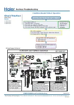
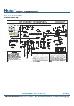
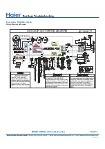
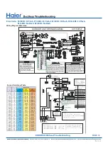
Page 50: ...Error Code E7 LED1 15 Flash Wiring Diagram Reference PAGE 50 ERROR CODES and Troubleshooting ...
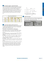
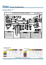
Page 57: ...PAGE 57 Ambient Defrost and Pipe Sensor Tables Discharge Sensor Tables ...

