


IV.
OPERATING SYSTEMS
4.8D
OPERATING SYSTEMS CONTINUED
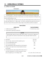
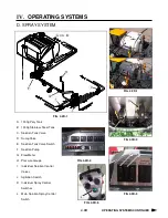
D. SPRAY SYSTEMS
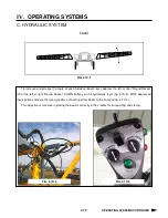
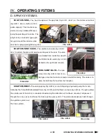
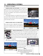
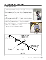
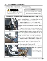
FENCE ROW APPLICATOR–
To operate the fence row nozzle,
locate the fence row switch on the console (fig. 4.8D-1) If you wish to turn
on the right fence row nozzle, depress the top of the fence row switch. To
turn on the left fence row, depress the bottom of the switch. To turn either
fence row nozzle off, return the switch to the center position.
As you engage either fence row you may notice a drop in solution
pressure.
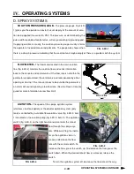
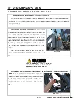
A pair of amber L.E.D. lights mounted on the transom (fig.
4.7D-2), on either side of the boom solution valve indicator
lights, will inform the operator of fence row status. If the left
fence row nozzle is ON, the left amber L.E.D. light will be on. If
the right fence row nozzle is ON, the right amber L.E.D. light
will be on. If neither amber L.E.D. light is on, there is no solu-
tion being applied through the fence row nozzles.
FIG. 4.8D-1
FIG 4.7D-2
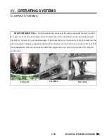
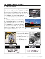
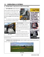
HAND WASHING SYSTEM–
Fill
the hand wash tank (fig. 4.8D-3) with
fresh water only! The hand wash
valve is located under the left side of
the sprayer (fig. 4.8D-4). Remember
to close the valve before refilling.
FIG 4.8D-3
FIG 4.8D-4
Summary of Contents for STS 10
Page 119: ...9 9 IX TROUBLE SHOOTING NOTES...
Page 127: ...NOTES NOTES...


