


IV.
OPERATING SYSTEMS
4.3D
OPERATING SYSTEMS CONTINUED
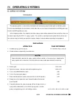
D. SPRAY SYSTEMS
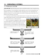
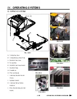
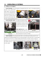
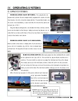
SOLUTION TANK–
You have the option of the poly tank (fig. 4.3D-1, item 1) or the stainless steel tank
(fig. 4.3D-1, item 2), both are 1000
gallon capacity. Their functions are
similar, the only notable difference
being the plumbing of the tanks. The
poly tank has an eductor type agita-
tion system and the stainless steel
tank has a sparge type agitation system.
FIG. 4.3D-1
2
1
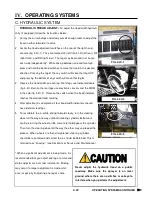
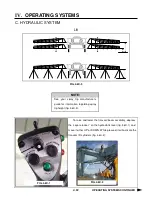
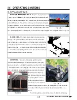
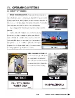
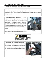
SOLUTION TANK VALVE–
The solution tank valve (fig. 4.3D-2,
item 1) controls the amount of solution coming out of the tank. The valve
is controlled from inside the cab with
the TANK VALVE switch (fig. 4.3D-3)
located on the right hand console.
TANK SUMP VALVE–
The tank
sump valve (fig. 4.3D-2, item 2) is a
ball type valve that has to be turned on and off manually. This valve is to
allow the fluid into the tank from the fill option.
FIG 4.3D-2
2
1
FIG 4.3D-3
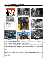
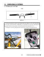
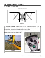
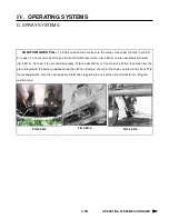
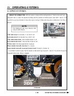
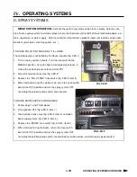
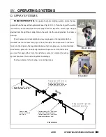
SOLUTION PUMP–
The solution pump (fig. 4.3D-4) is a centrifugal type hydraulic pump that is con-
trolled by the Pulse Width Modulated Valve (fig. 4.3D-5) and the Raven console (fig. 4.3D-6). The pump draws
the solution out of the tank at a rate determined during the calibration of the Raven console. It dispenses it
through the many valves and hoses that make up the spray system. The pump also dispenses fluids through
the agitation system and
the rinse systems.
FIG. 4.3D-4
FIG. 4.3D-5
FIG. 4.3D-6
Summary of Contents for STS 10
Page 119: ...9 9 IX TROUBLE SHOOTING NOTES...
Page 127: ...NOTES NOTES...


