

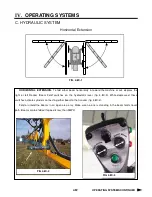
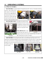
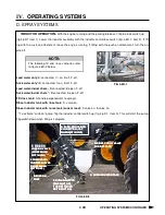
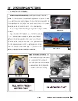


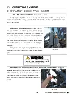

AGITATION–
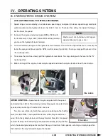
The speed of the sparge agitation system
(stainless steel tank option) or the eductor agitation system (poly
tank) is controlled by a variable flow solution valve (fig. 4.4D-3, item
1) mounted on the solution pump (fig. 4.4D-3, item 2). The agitation
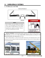
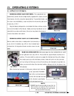
switch (fig. 4.4D-4) on the right hand console controls the rate of
flow through the sparge sys-
tem. While watching the indica-
tor on the agitation valve, in-
crease or decrease the flow
rate with the control switch. To
increase the flow, press the switch up. To decrease the flow, press the
switch down. When the desired rate of flow is achieved, release the
switch.
To turn the agitation system off, decrease the flow rate all the way.
FIG 4.4D-4
IV.
OPERATING SYSTEMS
4.4D
OPERATING SYSTEMS CONTINUED
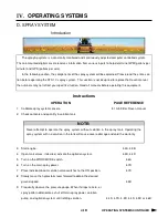
D. SPRAY SYSTEMS
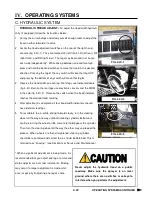
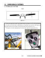
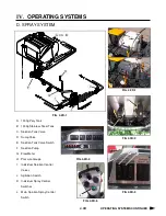
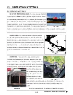
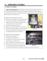
SOLUTION PRESSURE GAUGE–
The pressure gauge (fig. 4.4D-
1) gives you the operator a constant visual display of the amount of solu-
tion being applied (measured in PSI). The pressure, as determined by the
pulse width modulated control valve, will vary according to ground speed.
If applying solution manually, the solution pressure gauge visually informs
the operator of needed manual adjustments. The gauge also shows when
there is a drop in pressure indicating that the solution tank maybe empty or there is a problem with the system.
FIG. 4.4D-1
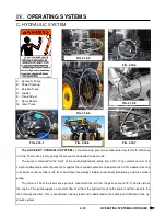
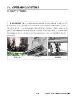
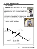
FLOW METER–
The flow meter located in the main solution
line (fig. 4.4D-2) monitors the solution flow and sends information
back to the console and control valve. If the flow rate is not within the
parameters programmed, the control valve will compensate by either
opening or closing. If the rate continues to be outside the parameters
an alarm will sound signaling a low flow rate. (See the Raven Console
guide for more information on low flow limit)
FIG. 4.4D-3
1
2
FIG. 4.4D-2
Summary of Contents for STS 10
Page 119: ...9 9 IX TROUBLE SHOOTING NOTES...
Page 127: ...NOTES NOTES...


