


12
5.52.653.00.01.06
Records must be kept of all test results and measures taken.
12.2
Monitoring
The monitoring and servicing intervals stated are valid for operation under normal conditions and single-shift
operation. In case of severe operating conditions (e.g. frequent operation with full load) or special
environmental conditions (e.g., heat, dust, etc.), the intervals must be shortened correspondingly
12.3
Brake motor
Electric driven trolleys from 15t are equipped with a brake motor
Connection voltage for the brake 400 VAC
Coil voltage: 180 VDC
trolley
Capacity
t
Brake
type
Nominal brake
moment
Nm
Nominal air gap
mm
air gap
max.
mm
friction lining thick-
ness
min.
mm
15-50
BFK 06
4
0,2
0,5
1,5
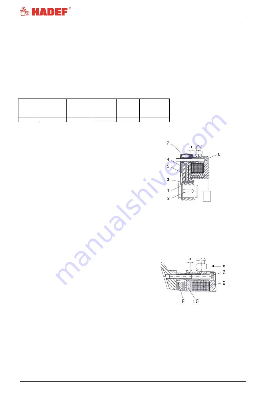
12.3.1
Assembling the brake
1 Insert the retaining ring (1) into the shaft slot.
2 Insert the feather key (2) into the motor shaft.
3 Fix hub (3) with retaining ring (1).
4 Assemble the friction plate (4) if existent.
5 Push the rotor (5) onto the hub (3).
6 Lock the magnet body with the 3 fastening
screws (6).
7
Set air gap “a” (refer to “adjusting the air gap”)
8 Assemble the dust-protection ring (7) if
existent.
9 Electric connection
Illustration 8
12.3.2
Disassembly of the brake
Disassembly is performed in reverse order to the assembly.
12.3.3
Adjusting the air gap
View "X" on the brake.
1 Loosen the locking screws (6) by half a turn.
2 Turn the cap screws (8) into the magnetic body
(9) anti-clockwise.
3 By turning the locking screws (6) clockwise,
move the magnetic body (9) towards the
anchor plate (10) using a feeler gauge until
nominal air gap “a” is reached (see table).
4 Unscrew the cap screws (8) from the magnetic
body clockwise.
5 Tighten the locking screws (6).
6 Check the air gap again and re-adjust if
necessary.
Illustration 9