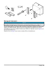
Electrical installation
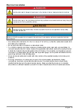
D A N G E R
Electrocution hazard. Always remove power to the instrument before making electrical connections.
D A N G E R
Electrocution hazard. Use only fittings that have the specified environmental enclosure rating. Obey the
requirements in the Specifications section.
W A R N I N G
Electrical shock hazard. Externally connected equipment must have an applicable country safety
standard assessment.
N O T I C E
Make sure that the equipment is connected to the instrument in accordance with local, regional and national
requirements.
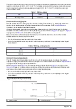
• Use cables with a diameter of 4.3 to 11.4 mm (0.17 to 0.45 in.) so that the cable strain reliefs hold
the cables when tightened.
• Do not put more than one cable in a cable strain relief.
• To connect conduit to a terminal, replace an installed cable strain relief with a conduit fitting. To
connect conduit to the I/O module, replace the applicable cable strain relief with a sealing conduit
to bond the conduit to the bonding plate of the I/O module. For a reliable, low impedance ground
connection, an independent ground wire with equivalent gauge can be pulled and attached at the
ground lug terminal on the bonding plate.
• Close all unused cable strain reliefs with rods, cables or the supplied sealing cords to keep out
moisture.
• For relay connections, it is necessary to use a 20 A circuit breaker (at maximum). Relay
connections must have a local disconnection device. The disconnection device must clearly
identify that this device is the disconnection device. Make sure that the device is in a location
where there is sufficient clearance around it to make connections and to do maintenance tasks.
English
9
Summary of Contents for IO9000
Page 2: ...English 3 Français 19 Español 37 Português 54 中文 72 日本語 88 2 ...
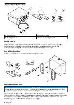
Page 7: ...Figure 2 Wall mounting English 7 ...
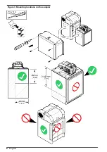
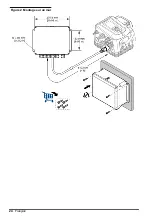
Page 8: ...Figure 3 Mounting locations on the sampler 8 English ...
Page 24: ...Figure 2 Montage sur un mur 24 Français ...
Page 25: ...Figure 3 Emplacements de montage sur l échantillonneur Français 25 ...
Page 42: ...Figura 3 Ubicaciones de montaje en el tomamuestras 42 Español ...
Page 59: ...Figura 2 Montagem na parede Português 59 ...
Page 60: ...Figura 3 Locais de montagem no amostrador 60 Português ...
Page 76: ...图 2 墙面安装 76 中文 ...
Page 77: ...图 3 采样仪上的安装位置 中文 77 ...
Page 79: ...拆下护盖 按照如下图示步骤拆下护盖 布线概述 图 4 显示了布线连接以及保险丝位置 请参阅 图 5 准备和安装电线 中文 79 ...
Page 93: ...図 3 サンプラーの取り付け場所 日本語 93 ...
Page 105: ......


