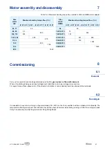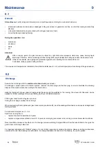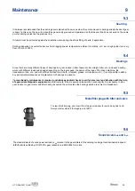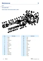
Installation of gear reducer
5
Attention!
During the running the gear reducers could have hot surfaces; Always wait that the gear reducer or the
gearmotor to cool before carrying out any operations.
Further technical documentation can be downloaded from our website www.rossi.com.
Fitting of components to shaft ends
It is recommended that the bore of parts keyed to low speed shaft ends is machined to K7 tolerance (H7 when load is uniform
and light).
Before mounting, thoroughly clean mating surfaces with proper antirust products, and lubricate against seizure and fretting
corrosion.
Installing and removal operations should be carried out with pullers and jacking screws using the tapped hole at the shaft butt-end.
Tightening torques for fastening bolts (feet, fl ange, accessories) and for plugs
Unless otherwise specifi ed, it is normally suffi cient to use class 8.8 screws; the following cases are an exception, for which
screws with strength class 10.9 must be used:
•
iC 372 - iC 373 FE with fl ange F312
•
iC 472 - iC 473 FE with fl ange F414
•
iC 572 - iC 573 FE with fl ange F516
Before tightening, carefully degrease the screws; in the event of heavy vibrations, heavy duties, frequent drive inversions apply
a thread-braking seal type LOCTITE or similar.
Fastening
bolts
Tightening torque Ms
for bolts for foot and fl ange fastening
N m
cl. 8.8
cl. 10.9
M4
2.9
4
M5
6
8.5
M6
11
15
M8
25
35
M10
50
70
M12
85
120
M14
135
190
M16
205
290
M18
280
400
M20
400
560
M22
550
770
M24
710
1000
Frame size
gear reducer
Tightening torque Ms
for oil drain and breather plugs
Plug threading
dimension
Ms
N m
iC 27 ... iC 67
M10 x 1
8
iC 77, iC 87
M12 x 1,5
14
iC 97
M22 x 1,5
45
Table 5.2.2 Tightening torques for oil drain and fi ller plugs
Table 5.2.1 Tightening torque for fastening bolts
5.2
15
UT.D 208-2021.12-EN


