


Lubrication
6
Important!
Check the mounting position, taking into account that if the gear reducer is installed in a mounting position other than
that indicated on the name plate, this may require topping up through the hole provided, the quantity of lubricant corresponding to
size x and indicated in the following tables.
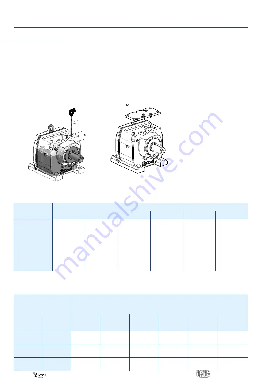
Measure x as shown in fi g. 6.3.1, after ensuring that you have removed any air pockets in the oil inside the gear reducer.
For iC 27 (always) and iF 47, iC 57 gear reducers in B6 mounting position, the oil level will be identifi ed by removing the cover
(see fi g. 6.3.1), positioning the gear reducer in the B3 mounting position. Calculate distance "x" between the oil level and the
cover resting surface.
Position the gear reducer or gearmotor in mounting position B3 in order to measure the oil level (quantity).
90°
UT
.C. 2438
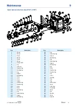
Fig. 6.3.1 Gear reducer oil quantity
Compare the "x" value measured (as in Fit. 6.3.1) with the max value provided by table 6.3.2.
Adjust the amount of oil if necessary.
Frame size
gear reducer
Oil quantity [l]
B3
B6
B7
B8
V5
V6
iC 272 - iC 273
0.25
0.5
0.5
0.5
0.7
0.7
iC 372 - iC 373
0.3
0.75
0.95
0.95
1.05
0.85
iC 472 - iC 473
0.7
1.5
1.5
1.5
1.65
1.6
iC 572 - iC 573
0.8
1.7
1.7
1.7
2.1
1.9
iC 672 - iC 673
1.1
1.8
2.0
2.8
2.9
2.4
iC 772 - iC 773
1.2
2.5
3.4
3.6
3.8
3.3
iC 872 - iC 873
2.3
6.3
6.5
7.2
7.2
6.4
iC 972 - iC 973
4.6
11.3
11.7
11.7
13.4
11.7
Table 6.3.1 Gear reducer oil quantity
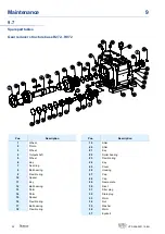
Gear reducer type
Maximum distance "x" [mm] between oil level
and gear reducer cover resting surface
Gear
reducer size
No. of
reduction
stages
B3
B6
B7
B8
V5
V6
iC 27
2
74 ± 1
45 ± 1
45 ± 1
45 ± 1
22 ± 1
22 ± 1
3
76 ± 1
42 ± 1
42 ± 1
42 ± 1
19 ± 1
19 ± 1
iC 47
2
-
39 ± 1
-
-
-
-
3
-
32 ± 1
-
-
-
-
iC 57
2
-
32 ± 1
-
-
-
-
3
-
28 ± 1
-
-
-
-
Table 6.3.2 Maximum distance "x" measurement
6.3
Oil (quantity) levels
22
UT.D 208-2021.12-EN


