12
96-0112 Rev W
July 2010
tt-10 (tl-4)
Removal
1. Turn off the machine. Turn off and disconnect shop air. Remove the T outlet
from the air regulator and reinstall the elbow fitting. Reconnect lube system air
line to this outlet.
2. Remove the TT-10 rear cover.
3. Disconnect all cables, coolant and the air line from the turret. Detatch the
turret cable carrier from its bracket.
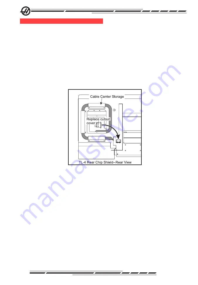
4. The cables and cable carrier can be stored as a unit on the back side of the
rear chip shield. See the following illustration. Replace the cutout cover and
secure with the screws used for the cable carrier.
5. Remove the mounting bolts. Install eyebolts and use a suitable lifting device
to remove the turret from the lathe.
6. Restore any previous coolant connection before proceeding.
Reinstallation
1. Clean the cross slide surface. Install eyebolts and use a suitable lifting
device to mount the TT-10 unit to the cross slide plate using four .75-10 x 2.75”
hex head bolts (retrofits on machines built before June 2008 will require .625”
shoulder bolts). The bolts should be snug, but not fully torqued at this point.
2. Remove the rear cover of the TT-10. Secure the cable carrier bracket to the
inside of the turret casting using two .25-20 x .5” BHCS.
3. Install the cable carrier between the TT-10 and the rear chip shield cutout.
Secure with four .25-20 x .5” BHCS at each end (the screws at the chip shield
end secure the cable carrier and the tray to the chip shield). Wrap the cables
where they exit into the turret. Pull any excess cable back and wrap them in
individual loops in the control cabinet. Close the Z-axis cable carrier.


