10
96-0112 Rev W
July 2010
8. To correct level alignment errors, surface grind or mill the shims to the ap
-
propriate thickness. The two surfaces must be parallel within .002” (0.051 mm).
9. Re-install the shims in their appropriate locations. If the tool center is below
spindle center after grinding, shim stock may be placed between the shim and
tool changer housing to restore the height.
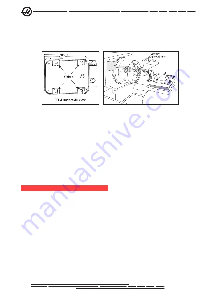
Shim Locations
Steps 10-13
10. Place the indicator tip against the inner vertical surface of the tool turret
(indicated by the shaded area on the illustration).
11. Jog the X-Axis and measure the alignment of the tool turret over the entire
surface.
12. Alignment error should not exceed 0.001” (0.025 mm) over 5.5” (140 mm)
travel.
13. Tap the base to correct any misalignment and tighten the turret mounting
bolts to 130 ft-lbs (176 Nm).
14. Re-verify alignment.
15. Change Setting 113 to “Auto”.
tt-20 (tl-3)
Removal
1. Turn off air to the turret at the regulator, then disconnect the air line and elec-
trical cable from the turret.
2. Remove the turret mounting bolts.
3. Install eyebolts into the threaded holes on both sides of the turret and use a
suitable lifting device and straps to lift the turret off of the riser block. Be sure
to lift the turret high enough to clear the dowel pins in the riser block before
moving it out. Note the number of shims used at each corner of the turret for
reinstallation.
4. Remove the riser block.
5. Change Setting 113 to either “TL Post” or “Gang TL” as appropriate.


