12
January 2004
POSIT
ION
DISPLAY
The POSITION Display shows the location of the machine axes in
X
,
Y
,
Z
,
A or B
axis positions in
any of the four different coordinate systems that are available. Pressing PAGE UP or PAGE DOWN
keys (or arrow up and arrow down keys) will select between the operator, work, machine, and dis-
tance-to-go position formats in large number format, or the one with all four position displays together in small
number format.
If one of the four large caracter displays listed below, is the last one to be selected, itll then be the one seen in
CURNT COMDS or CALC displays when they are selected.
When in handle jog, on any of the other large character display pages, the selected axis will be blinking.
The following are the five position display pages in the control:
POSITION
PAGE
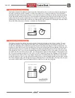
This display shows the four displays simultaneously in small characters. The other displays are shown in large
characters. The PAGE UP and PAGE DOWN keys will change displays. The coordinates displayed (operator,
work, machine, or distance to go) are selected using the cursor arrow, or page
up
and
down
keys. In this
POSITION display, any axis that is at machine zero position, the axis letter will be highlighted.
POS-OPER
PAGE
This display is for the operator/setup person to use as desired, and is not directly used by the control for any
program positioning functions. In any of the modes, when your on this page, you can select the letter
X
,
Y
,
Z
,
A
or
B
and then press the ORIGIN button. That axis letter will then br set to zero, for use as a reference
position only. Doing this will not effect the active program in any way. This reference will then show a position
display relative to that selected zero position. You can also define a location with a specific number. Enter an
axis letter with a number (
X-3.125
), and press ORIGIN, to enter an axis position at that number for reference
use only. This new number will not change until you set it with ORIGIN again or you power off the machine.
POS-WORK
PAGE
This display shows how far away the tool is from the work offset part zero
X
,
Y
,
Z
axis location being used on a
programmed part. On power-up, it will display the distance value from the work offset G54 default part zero
locationautomatically. It can then be changed while running a program in MEM or MDI with G54 through G59,
G110 through G129, G154 P1-P99, or with a G52 or G92 command. The machine will then use that coordinate
location defined with that work offset as a part zero reference to run a programmed part.
POS-MACH
PAGE
This is the machine zero coordinate location display that is automatically set when you send the machine
home with Power-Up/Restart (or AUTO ALL AXES), on the first ZERO RET after powering up machine. It
cannot be changed by the operator or any work coordinate location. It will always show the distance from
machine zero. If you would like to position to a location defined from machine zero, then use a non-modal G53
command. When using a G53 command, it is non-modal, so the next command line will revert back to the
previously recognized work offset.
POSIT
Summary of Contents for EC Series
Page 1: ...January 2004 ...
Page 7: ...V I January 2004 ...
Page 125: ...118 January 2004 ...
Page 126: ......

