F/N 521599 Oct 07
© 2007 ICS, Blount Inc.
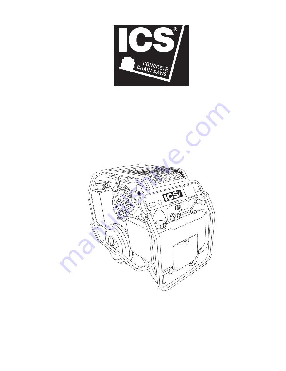
OPERATOR’S MANUAL
P95
MultiFlow Hydraulic Powerpack
Page 1: ...F N 521599 Oct 07 2007 ICS Blount Inc OPERATOR S MANUAL P95 MultiFlow Hydraulic Powerpack...
Page 2: ......
Page 3: ...07 ICS Blount Inc P95 OPERATOR S MANUAL 3 TABLE OF CONTENTS SYMBOLS LABELS 4 SAFETY 5 TECHNICAL SPECIFICATIONS 6 LABELS 7 REQUIREMENTS 8 OPERATION 10 MAINTENANCE 15 CONTROLLER FAULT CODES 16 TESTING 1...
Page 4: ...njury A potentially hazardous situation exists which if not avoided may result in minor or moderate injury or property damage A potential situation exists which if not avoided may result in product or...
Page 5: ...ng used Do not inspect hoses and ttings for leaks by using bare hands Pin hole leaks can penetrate the skin NEVER OPERATE THE POWER UNIT IN A CLOSED SPACE Inhalation of engine exhaust can be fatal Do...
Page 6: ...inches 91 4 cm Width 23 inches 58 4 cm Height 29 5 inches 74 9 cm Weight wet 330 lbs 149 6 kg Fuel Tank Capacity 7 gal 26 5 ltr Esitmated Gas Consumption per Hour 1 3 gal 4 ltr Hydraulic Reservor Cap...
Page 7: ...F N 521599 Oct 07 2007 ICS Blount Inc P95 OPERATOR S MANUAL 7 Labels TOOLS STICKERS AND TAGS ICS Dash Decal Single Curcuit Single Curcuit...
Page 8: ...OR CERTIFIEDAS NON CONDUCTIVE WHEN USING HYDRAULIC TOOLS ON OR NEAR ELECTRIC LINES MAY RESULT IN DEATH OR SERIOUS INJURY 2 FOR PROPERAND SAFE OPERATION MAKE SURE THATYOU HAVE BEEN PROPERLYTRAINED IN...
Page 9: ...rence of between ambient and fluid temps 3 hp 2 24 kW 40 F 22 C 5 hp 3 73 kW 40 F 22 C 7 hp 4 47 kW 40 F 22 C 6 hp 5 22 kW 40 F 22 C NOTE DO NOT operate the tool at oil temperature above 140 F 60 C Op...
Page 10: ...nimum Pour Point 10 F 23 C Min cold start up Viscosity Index ASTM D 2220 140 Min Demulsibility ASTM D 1401 30 Minutes Max Flash Point ASTM D 92 340 F 171 C Min Rust Inhibition ASTM D 665 A B Pass Oxid...
Page 11: ...ing of 2500 psi 172 bar Do not use galvanized pipe ttings or black pipe ttings Use thread tape or pipe joint compound when installing quick disconnect couplings to hose or tool ttings Follow the instr...
Page 12: ...2007 ICS Blount Inc F N 521599 Oct 07 P95 OPERATOR S MANUAL 12 operation CONTROL PANEL...
Page 13: ...UTO ON position the oil ow is regulated automatically when the trigger on the tool activated When the tool is not being used the engine will return to idle automatically after a 10 second delay This s...
Page 14: ...the tool move the ow selector switch to the OFF position FOR 8 gpm 30 l min OPERATION For 8 gpm 30 l min operation select mode of operation with the Throttle Control Switch either auto idle on or the...
Page 15: ...the water at the bottom of the container Each day check hydraulic lines and ttings for leaks kinks etc Do not use your hand to perform this check Change the hydraulic lter element every 200 hours of o...
Page 16: ...to actuator 2 Attach jumper wires from battery to RED and GREEN wires to actuator A Attach 12 volt positive to RED wire B Attach 12 volt negative to GREEN wire 3 Actuator should move throttle lever to...
Page 17: ...lerator position idle switch conflict NO Have engine serviced by an Authorized ICS Dealer 8 Controller unit failed YES Have engine serviced by an Authorized ICS Dealer 9 Limiting excessive actuator cu...
Page 18: ...l warm 6 Switch the ow selector switch to 5 or 8 gpm depending on which ow you are testing 7 With the engine at the programed speed the test ow gauge should read 4 6 gpm 15 23 l min or 7 9 gpm 26 5 34...
Page 19: ...ON Check that the flow selector switch is set to 5 or 8 gpm Incorrect hose connection tool Make sure the tool hose circuit goes from left pressure fitting to tool and back to the right fitting return...
Page 20: ...2007 ICS Blount Inc F N 521599 Oct 07 ICS Blount Inc 4909 SE International Way Portland OR 97222 Tel 800 321 1240 Fax 503 653 4393 icsbestway com P95 OPERATOR S MANUAL...