


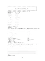


49
Starting application at 0x00100000 ...
TLB init OK.
LBC init OK.
LAW init OK.
Bsp init start...
MMU init OK.
CRC init OK.
Frame data init OK.
Connect IRQ 0 OK.
Enable IRQ 0 OK.
Connect IRQ 1 OK.
Enable IRQ 1 OK.
Connect IRQ 2 OK.
Enable IRQ 2 OK.
Connect IRQ 4 OK.
Enable IRQ 4 OK.
Connect IRQ 5 OK.
Enable IRQ 5 OK.
Connect IRQ 6 OK.
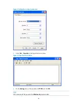
After the switch completes booting the applications, the following information appears on the terminal
screen:
Press ENTER to get started.
Press
Enter
to begin configuring the switch at the prompt:
<H3C>
NOTE:
•
The S9500E switches provide a command line interface (CLI). For more information about the CLI, see
H3C S9500E Switch Series Fundamentals Configuration Guide.
•
The output depends on your switch model.
Verification after power-on
H3C recommends that you check the following conditions after the switch is powered on:
•
The cooling system is working. You should be able to hear fan rotation noise and feel air being
blown out.
•
All the LEDs are functioning properly.
Table 14
LED status when the switch operates properly
Part LED Name/Color
Status
MPU
MPU status LED
SFC (green)
Steady on
ACT (green)
•
Active MPU
—Steady on
•
Standby MPU
—Off
RUN (green)
Flashing
LPU status LED
RUN (green)
Flashing


