


9
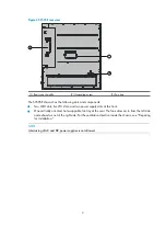
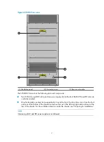
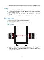
Figure 8
S9512E rear view
(1) Rear cover handle
(2) Grounding screw
(3) Fan tray and handle
The S9512E chassis has the following slots and components:
•
Two MPU slots, 12 LPU slots, and two power supply slots at the front.
•
Two vertically oriented, hot swappable fan trays at the rear. The fans draw air in from the left side
and exhaust air out of the right side. For the ventilation direction inside the chassis, see "Preparing
for installation."
NOTE:
Intermixing of AC and DC power supplies is not allowed.
Backplane
The backplane of an S9500E switch is located inside the chassis. It provides high-speed data switching
and exchanges management and control signals between MPUs and LPUs. The backplane provides the
following capabilities:
•
Provides communication channels for signal exchange between cards.
•
Supports hot-swapping of cards.
•
Identifies card type.


