


1
Product overview
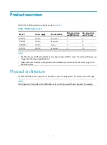
The H3C S9500E switches include the models in
Table 1
S9500E switch models
Model Power
supply
Slot orientation
Main processing
unit (MPU) slots
Line processing
unit (LPU) slots
S9505E AC/DC Horizontal
2
5
S9508E AC/DC Horizontal
2
8
S9508E-V AC/DC Vertical
2
8
S9512E AC/DC Horizontal
2
12
NOTE:
•
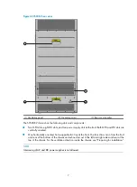
The LPU slots are for Ethernet interface cards, base cards, and OAA cards. For card specifications, see
"Appendix A Technical specifications."
•
Unless otherwise stated, the configuration and installation procedures in this document apply to all
S9500E switches.
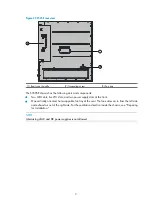
Physical architecture
An H3C S9500E chassis comprises a backplane, power supply system, fan system, and card cage.
NOTE:
The diagrams in this guide are for illustration only, and AC-powered chassis are used for example.


