
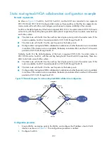


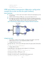


218
4.
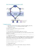
Configure VRRP on Switch B.
<SwitchB> system-view
[SwitchB] interface vlan-interface 2
# Create VRRP group 1, and configure the virtual IP address 10.1.1.10 for the group.
[SwitchB-Vlan-interface2] vrrp vrid 1 virtual-ip 10.1.1.10
5.
Verify the configuration
After configuration, ping Host B on Host A, and you can see that Host B is reachable. Use the
display
vrrp
command to view the configuration result.
# Display detailed information about VRRP group 1 on Switch A.
[SwitchA-Vlan-interface2] display vrrp verbose
IPv4 Standby Information:
Run Mode : Standard
Run Method : Virtual MAC
Total number of virtual routers : 1
Interface Vlan-interface2
VRID : 1 Adver Timer : 1
Admin Status : Up State : Master
Config Pri : 110 Running Pri : 110
Preempt Mode : Yes Delay Time : 0
Auth Type : None
Virtual IP : 10.1.1.10
Virtual MAC : 0000-5e00-0101
Master IP : 10.1.1.1
VRRP Track Information:
Track Object : 1 State : Positive Pri Reduced : 30
# Display detailed information about VRRP group 1 on Switch B.
[SwitchB-Vlan-interface2] display vrrp verbose
IPv4 Standby Information:
Run Mode : Standard
Run Method : Virtual MAC
Total number of virtual routers : 1
Interface Vlan-interface2
VRID : 1 Adver Timer : 1
Admin Status : Up State : Backup
Config Pri : 100 Running Pri : 100
Preempt Mode : Yes Delay Time : 0
Auth Type : None
Virtual IP : 10.1.1.10
Master IP : 10.1.1.1
The output shows that in VRRP group 1, Switch A is the master and Switch B is a backup. Packets from
Host A to Host B are forwarded through Switch A.
# Shut down the uplink interface VLAN-interface 3 on Switch A.
[SwitchA-Vlan-interface2] interface vlan-interface 3
[SwitchA-Vlan-interface3] shutdown
After shutting down the uplink interface on Switch A, you can still successfully ping Host B on Host A. Use
the
display vrrp
command to view information about VRRP group 1.