


166
# Display the detailed information of the VRRP group on Switch B.
[SwitchB-Vlan-interface3] display vrrp ipv6 verbose
IPv6 Standby Information:
Run Mode : Standard
Run Method : Virtual MAC
Total number of virtual routers : 2
Interface Vlan-interface2
VRID : 1 Adver Timer : 100
Admin Status : Up State : Backup
Config Pri : 100 Running Pri : 100
Preempt Mode : Yes Delay Time : 0
Auth Type : None
Virtual IP : FE80::10
1::10
Master IP : FE80::1
Interface Vlan-interface3
VRID : 2 Adver Timer : 100
Admin Status : Up State : Master
Config Pri : 110 Running Pri : 110
Preempt Mode : Yes Delay Time : 0
Auth Type : None
Virtual IP : FE90::10
2::10
Virtual MAC : 0000-5e00-0202
Master IP : FE90::2
The output shows that in VRRP group 1 Switch A is the master, Switch B is the backup and hosts with the
default gateway of 1::10/64 accesses the Internet through Switch A; in VRRP group 2 Switch A is the
backup, Switch B is the master and hosts with the default gateway of 2::10/64 accesses the Internet
through Switch B.
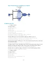
VRRP load balancing mode configuration example
Network requirements
•
Switch A, Switch B, and Switch C belong to VRRP group 1 with the virtual IPv6 addresses of
FE80::10 and 1::10.
•
Hosts on network segment 1::/64 learn 1::10 as their default gateway through RA messages sent by
the switches. Use the VRRP group to make sure that when a gateway—Switch A, Switch B, or Switch
C—fails, the hosts on the LAN can access the external network through another gateway.
•
VRRP group 1 works in load balancing mode to make good use of network resources.
•
Configure a track entry on Switch A, Switch B, and Switch C respectively to monitor their own
VLAN-interface 3. When the interface on Switch A, Switch B, or Switch C fails, the weight of the
corresponding switch decreases so that another switch with a higher weight can take over.