


8-8
Replacing an optical fiber for a multi-chassis fabric module
1.
Wear an ESD wrist strap. Make sure the wrist strap makes good skin contact and is reliably
grounded.
2.
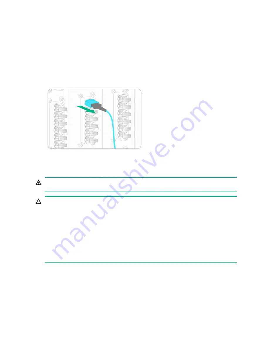
Hold the front end of the MTP connector and remove the optical fiber from the fiber port.
3.
Connect a new optical fiber. For the connection procedure, see "Connecting an optical fiber to a
multi-chassis fabric module."
If you are not to install a new optical fiber in the fiber port, insert the dust plug into the port.
Figure8-8 Removing an optical fiber with an MTP connector
Replacing a fan tray
WARNING!
The fan trays are hot swappable. Ensure electricity safety when you hot swap a fan tray.
CAUTION:
•
The router provides 33 fan tray slots. For good cooling performance, install fan trays in all fan tray
slots.
•
The router uses N+1 fan tray redundancy. When a fan tray fails, the router can dissipate heat
normally. However, replace the faulty fan tray immediately as a best practice. Keep the faulty fan
tray in the chassis until a new fan tray is ready to be installed.
•
Before powering on the router, make sure all fan tray slots are installed with fan trays correctly.
•
The fan trays in the top four rows (FAN 1 to FAN 12), in the middle three rows (FAN 13 to FAN
21), and in the bottom four rows (FAN 22 to FAN 33) power up after a three-second delay,
two-second delay, and four-second delay, respectively upon power-up of the router. Before a fan
tray powers up, its OK/FAIL LED is red.
To replace a fan tray:
1.
Prepare an antistatic mat to place the removed fan tray.
2.
Wear an ESD wrist strap. Make sure the wrist strap makes good skin contact and is reliably
grounded.
3.
Hold the fan tray handle and press the red part on the handle to pull the fan tray slowly out of the
slot.
4.
Turn over the fan tray and place it on the antistatic mat, with the bottom clasp facing up.
5.
Install a new fan tray. For the installation procedure, see "Installing fan trays."
Summary of Contents for CR19000-20
Page 11: ...1 5 Figure1 1 Chassis dimensions...
Page 39: ...2 9 Figure2 7 Securing the router to the rack...
Page 61: ...4 2 Figure4 1 Slot arrangement...
Page 84: ...6 5 Figure6 4 Installing an air filter...
Page 97: ...8 9 Figure8 9 Removing a fan tray...
Page 103: ...8 15 Figure8 18 Securing the new power tray...
Page 131: ...11 7 Figure11 8 Routing AC power cords...


