background image


8-5 

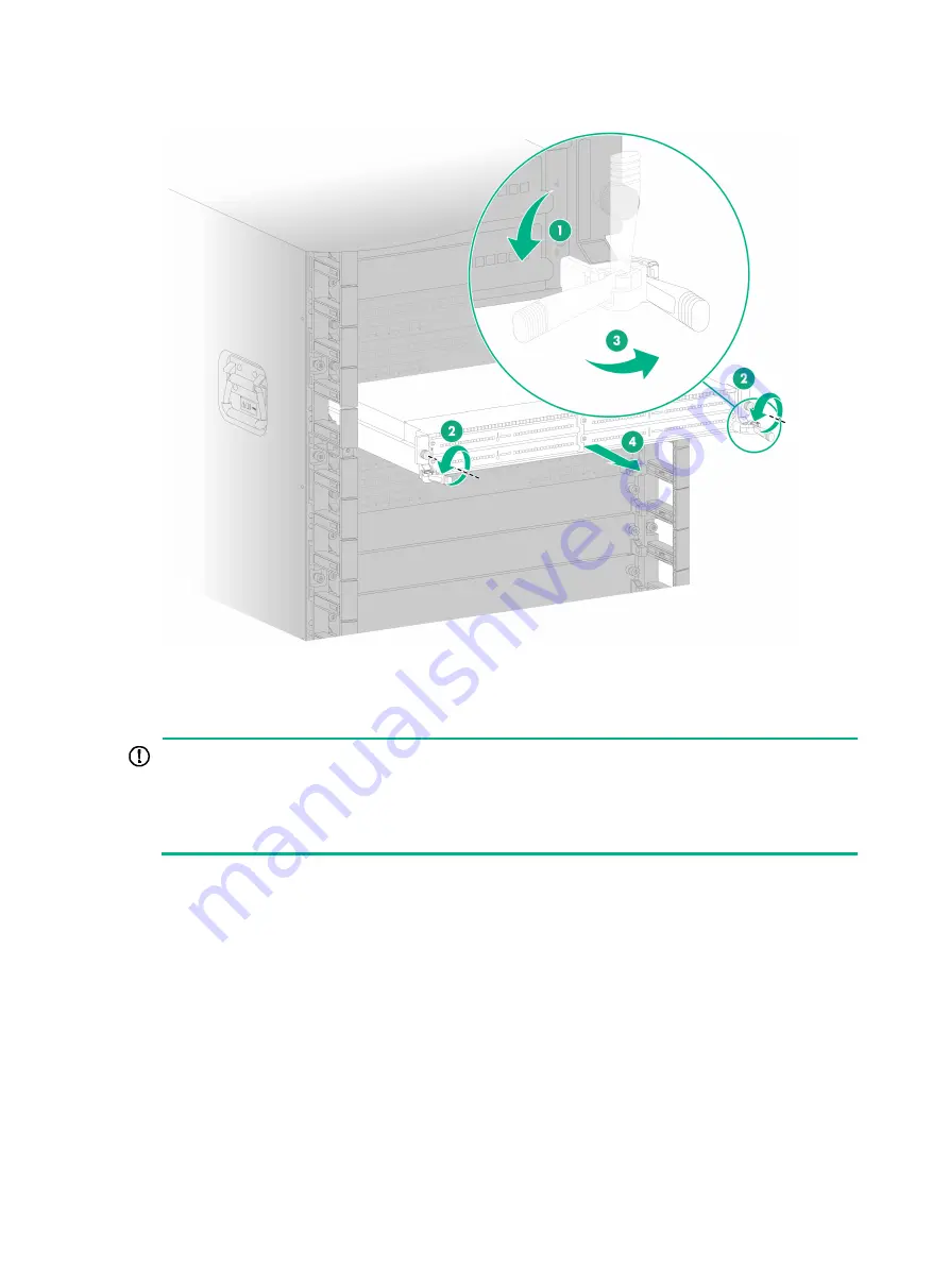
Figure8-4 Removing an interface module with ejector levers 


Replacing an interface subcard 


IMPORTANT: 

  If you are not to install a new interface subcard after removing the old one, install a filler panel in 

the slot. 

  When installing a filler panel, orient it with the blade of the screwdriver image on it facing 

upwards. First insert the filler panel right side into the slot, and then push the left side into the slot. 


1. 

Remove the cables from the interface subcard. 

2. 

Prepare an antistatic mat to place the removed interface subcard. 

3. 

Wear an ESD wrist strap. Make sure the wrist strap makes good skin contact and is reliably 
grounded. 

4. 

Use a Phillips screwdriver to loosen the captive screws on the interface subcard. 

5. 

Open the ejector levers on the interface subcard and then pull the interface subcard part way 
out of the slot. 

6. 

Supporting the interface subcard bottom with the left hand, slowly pull the interface subcard out 
of the slot along the guide rails with the right hand. 

7. 

Place the removed interface subcard on the antistatic mat. 

8. 

Install a new interface subcard. For the installation procedure, see "Installing interface 
subcards." 

Summary of Contents for CR19000-20

Page 1: ...H3C CR19000 20 Core Router Installation Guide New H3C Technologies Co Ltd http www h3c com Document version 6W103 20211022...

Page 2: ...respective owners Notice The information in this document is subject to change without notice All contents in this document including statements information and recommendations are believed to be acc...

Page 3: ...ments that you replace with actual values Square brackets enclose syntax choices keywords or arguments that are optional x y Braces enclose a set of required syntax choices separated by vertical bars...

Page 4: ...s Convention Description Represents a generic network device such as a router switch or firewall Represents a routing capable device such as a router or Layer 3 switch Represents a generic switch such...

Page 5: ...ardware model configuration or software version It is normal that the port numbers sample output screenshots and other information in the examples differ from what you have on your device Documentatio...

Page 6: ...Ladder safety 1 3 Examining the installation site 1 3 Weight support 1 3 Space 1 4 Cooling 1 6 Temperature and humidity 1 7 Cleanliness 1 8 Harmful gas limit 1 8 EMI 1 9 Grounding 1 9 Power supply 1 9...

Page 7: ...the router Use a screwdriver to fasten screws If you cannot install a removable component smoothly stop your operations and troubleshoot the issues preventing component damages caused by misoperations...

Page 8: ...al instruments when the router is operating Before you remove the optical fiber connector from a fiber port execute the shutdown command in interface view to shut down the port CAUTION Insert dust cap...

Page 9: ...injury Examining the installation site The router must be used indoors To ensure correct operation and long service life of the router verify that the installation site meets the generic operating en...

Page 10: ...58 in Chassis 850 mm 33 46 in Cable management bracket 90 mm 3 54 in Fan tray handle at the rear 40 mm 1 57 in As a best practice use a rack that meets the following requirements With dimensions H W...

Page 11: ...1 5 Figure1 1 Chassis dimensions...

Page 12: ...Make sure the following requirements are met The installation site has a good cooling system The air conditioners do not blow air directly onto the router The rack for the router can provide adequate...

Page 13: ...ow or changes dramatically the device reliability is reduced and its service lifetime is shortened High temperature can accelerate the aging of insulation materials and significantly lower the reliabi...

Page 14: ...le layer glass in windows and seal doors and windows with dust proof rubber strips Use screen doors and screen windows in the external side Keep the equipment room clean If the equipment room environm...

Page 15: ...l to lightning protection anti interference and ESD prevention Use a good grounding system for the router Make sure the resistance between the chassis and the ground is less than 1 ohm Power supply A...

Page 16: ...g weight of the router includes the chassis and packaging materials Determine a moving method for the chassis based on its shipping weight The packaging materials include wooden boards steel hinges st...

Page 17: ...owering on the router keep the router as it is take photos and keep the original packing materials padding materials and accessories When transporting moving and installing the router be careful not t...

Page 18: ...ghten the standard tongue as shown in Figure1 5 You can also use a wrench or claw hammer to straighten the standard tongue Figure1 5 Straightening a standard tongue 4 After straightening all standard...

Page 19: ...1 13 Figure1 6 Removing the plywood box lid and side panels 5 Unpack the wooden ramp place the ramp in front of the pallet and use U type fasteners to secure the ramp to the pallet front...

Page 20: ...ter soaking or corrosion The labels on the chassis are correct clear and complete The accessory box packages are intact and the number of the boxes is correct Moving the chassis to the installation lo...

Page 21: ...15 Figure1 8 Removing the screws on the hold down brackets that secure the dolly to the pallet 2 Adjust the levelling foot of the dolly so that the dolly wheels support the chassis as shown in Figure1...

Page 22: ...6 Figure1 9 Adjusting the levelling foot of the dolly 3 Push the chassis down over the wooden ramp slowly The router is high and heavy As a best practice use a minimum of four people to push the chass...

Page 23: ...Figure1 10 Pushing the chassis down over the wooden ramp 4 Detach the elevator bridge plate from the pallet and keep it secure for future use Figure1 11 Detaching the elevator bridge plate from the pa...

Page 24: ...om being stuck into the gap Figure1 12 Elevator bridge plate Figure1 13 Using the elevator bridge plate in a freight elevator 5 Move the chassis to a location close to the installation location and th...

Page 25: ...dolly wheels support the chassis 8 Move the chassis to the front of the rack and then detach the dolly from the chassis as follows a Use a Phillips screwdriver to remove the screws on the side of the...

Page 26: ...e rack before detaching the dolly from the chassis Ensure that the L type brackets are removed completely before rack mounting the router Keep the detached dolly secure for later moving Unpacking and...

Page 27: ...cushion out of the carton 2 Wear an ESD wrist strap and make sure the wrist strap is reliably grounded 3 Take the component out of the anti static bag 4 Check the items in the carton against the packi...

Page 28: ...eight of the router and the rack The slide rails can support the actual weight of the router Space There is a minimum clear height of 3 m 9 84 ft from the beam or the air duct to the floor in the equi...

Page 29: ...port lightning arresters are available Grounding The grounding specifications for the equipment room comply with national and industry standards All communication devices in the equipment room are rel...

Page 30: ...nstallation preparations 2 3 Rack mounting the router 2 3 Attaching slide rails to the rack 2 3 Optional Installing PDUs 2 3 Removing the top hood 2 4 Mounting the router in a rack 2 5 Installing fan...

Page 31: ...2 1 2 Installing the router The figures of router and components in the document are for illustration only Keep the packing boxes and packing bags for the chassis and components secure for future use...

Page 32: ...nstall modules Connect cables Verify the installation Check before and after power on Troubleshoot the router Power off the router Operating correctly Read safety recommendations Inspect the router Ex...

Page 33: ...Applicable slide rails Slide rail model Adjustment range Occupied space CR19000 20 600 kg 1322 75 lb LSXM1BSR 630 mm to 900 mm 24 80 in to 35 43 in 1 RU For information about installing the slide rail...

Page 34: ...n the left rack post align the two right installation holes of the PDU with that in the PDU bracket and use screws to secure the PDU to the bracket Then use the same method to secure the other end of...

Page 35: ...age nut installation holes according to the holes in the mounting brackets The mounting brackets are long Make sure the holes are correctly aligned and the cage nuts are installed securely Place the r...

Page 36: ...2 6 tape measure to align the holes in the mounting brackets with the holes on the rack post for installing cage nuts Figure2 4 Marking the cage nut installation holes...

Page 37: ...ck do not leave go of your hands immediately because this might tip and damage the router 6 All people work in cooperation to slide the router along the guide rails into the rack until the mounting br...

Page 38: ...2 8 Figure2 6 Rear pulling of the router 7 Use M6 screws provided with the router to secure the router to the rack posts as shown in Figure2 7...

Page 39: ...2 9 Figure2 7 Securing the router to the rack...

Page 40: ...after a three second delay two second delay and four second delay respectively upon power up of the router Before a fan tray powers up its OK FAIL LED is red The router uses N 1 fan tray redundancy Wh...

Page 41: ...rod Make sure the ground point on the rack is connected reliably to a grounding strip in the equipment room IMPORTANT The grounding cable provided with the router is NEBS compliant Connect the two hol...

Page 42: ...m blocking the mounting bracket mounting holes on the rack posts install cable management brackets after you mount the router in the rack The router comes with four types of cable management brackets...

Page 43: ...at the right side The following installs a cable management bracket at the right side To install a cable management bracket 1 If any cable guide hinders installation of the cable management bracket pr...

Page 44: ...anagement bracket with the lettering facing upward and then position the cable management bracket on the mounting bracket 4 Align the captive screws on the cable management bracket with the holes in t...

Page 45: ...r cord 3 4 Optional Attaching a two hole power lug to a DC power wire 3 8 Installing AC power supplies 3 8 Available AC power supplies 3 8 AC power supply configuration guidelines 3 9 Installing an AC...

Page 46: ...Available DC power supplies The PSR2000B 54D DC power supply is available for the router Table3 1 describes the PSR2000B 54D DC power supply specifications Table3 1 PSR2000B 54D DC power supply specif...

Page 47: ...ies is greater than the system power consumption with a 20 power surplus as a best practice Provide a circuit breaker or fuse for power input of each DC power supply Make sure each input line has a cu...

Page 48: ...3 Correctly orient the power supply 4 Align the power supply with the power supply slot Then slide the power supply along the guide rails into the slot until the latch locks the power supply in place...

Page 49: ...ver Reinstall the cover after connecting the power cord To prepare DC power cords yourself attach a two hole power lug to each DC power wire before connecting the DC power cord to the chassis See Opti...

Page 50: ...ack wires to the positive terminals marked with RTN and the blue wires to the negative terminals marked with NEG as shown in Figure3 6 As a best practice connect the DC power cords to the terminal blo...

Page 51: ...3 6 Figure3 7 Connecting power cords to the terminal blocks from left to right 1 Figure3 8 Connecting power cords to the terminal blocks from left to right 2...

Page 52: ...DC power supply system Connect the blue wires to the negative terminals marked with 48V and the black wires to the positive terminals marked with RTN 6 Reinstall the terminal block cover and then fast...

Page 53: ...e wire Then slide the open end of the two hole power lug over the exposed conductors of the power wire 3 Use a crimping tool to crimp the open end of the power lug tightly to the conductors of the wir...

Page 54: ...on based on the power input mode As a best practice configure N N dual power sources AC power supply redundancy Make sure N N is not larger than the total number of power supply slots N is the number...

Page 55: ...3 Correctly orient the power supply 4 Align the power supply with the power supply slot Then slide the power supply along the guide rails into the slot until the latch locks the power supply in place...

Page 56: ...To connect an AC power cord 1 Remove the protective plate over the power input area as shown in Figure3 14 Figure3 14 Removing the protective plate 2 Connect the AC power cord connector to the AC inp...

Page 57: ...the power input mode As a best practice configure N N dual power sources HVDC power supply redundancy Make sure N N is not larger than the total number of power supply slots N is the number of HVDC po...

Page 58: ...3 13 Connecting an HVDC power cord For information about connecting the power cord for a PSR3000B 54AHD power supply see Connecting an AC power cord...

Page 59: ...nt 4 1 Installing MPUs 4 3 Installing fabric modules 4 5 Installing interface modules 4 6 Installing an interface module that uses detachable ejector levers 4 7 Installing an interface module that use...

Page 60: ...f router and components in this document are for illustration only Slot arrangement LPU in Figure4 1 refers to an interface module SFU refers to a single chassis fabric module MSFU refers to a multi c...

Page 61: ...4 2 Figure4 1 Slot arrangement...

Page 62: ...ring filler panel installation and removal on an operating router If you are not to install an MPU in an MPU slot keep the filler panel in the slot The router has two MPU slots You can install one MPU...

Page 63: ...front panel until the brakes on its ejector levers touch the slot edges tightly 5 Close the ejector levers until they come in close contact with the front panel 6 Use a Phillips screwdriver to fasten...

Page 64: ...ic module avoid touching the connectors on the fabric module To prevent a filler panel from being drawn into the chassis when fan speed is high use both hands to grasp the filler panel by its two side...

Page 65: ...levers touch the slot edges tightly 6 Close the ejector levers until they come in close contact with the front panel 7 Use a Phillips screwdriver to fasten the captive screws on the fabric module Ins...

Page 66: ...ace module Do not hold detachable ejector levers to lift an interface module Figure4 6 Detachable ejector lever To install an interface module that uses detachable ejector levers 1 Wear an ESD wrist s...

Page 67: ...t and push it steadily into the slot along the guide rails until about half of the module is in the slot Figure4 8 Installing an interface module that uses detachable ejector levers 5 Attach the eject...

Page 68: ...e ejector levers Place the ejector lever back on their holders and keep them secure for future use Figure4 11 Removing an ejector lever Installing an interface module that uses general ejector levers...

Page 69: ...ler panel by its two sides during filler panel installation and removal on an operating router For the interface subcard compatibility with interface modules see H3C CR19000 20 Core Router Hardware In...

Page 70: ...art on the front panel until you cannot push it any further 6 Close the right ejector lever until it comes in close contact with the front panel 7 Use a screwdriver to fasten the captive screw on the...

Page 71: ...ted pair cable 5 2 Connecting an Ethernet cable 5 3 Connecting cables to fiber ports 5 3 About transceiver modules and optical fibers 5 3 Installing transceiver modules and optical fibers 5 4 Connecti...

Page 72: ...ables are mainly used in 1000 Mbps Ethernet networks Category 6 cables provide a transmission frequency of 1 MHz to 250 MHz and improve the performance on crosstalk and return loss A fine better retur...

Page 73: ...cable Table5 1 Straight through cable pinouts Pinout No A B 1 Orange white Orange white 2 Orange Orange 3 Green white Green white 4 Blue Blue 5 Blue white Blue white 6 Green Green 7 Brown white Brown...

Page 74: ...9000 20 Core Router Hardware Information and Specifications Connecting cables to fiber ports About transceiver modules and optical fibers To connect a fiber port install an SFP SFP XFP CFP2 QSFP28 or...

Page 75: ...ake the transceiver module by its two sides and push the end without the bail latch gently into the port until it is firmly seated in the fiber port Use tweezers to insert the transceiver module into...

Page 76: ...transceiver module in each cluster port You can connect an optical fiber with an MTP connector to a cluster port on the multi chassis fabric module directly To connect an optical fiber to a cluster po...

Page 77: ...es No coaxial connectors and 75 ohm E1 adapter cables are provided with interface subcards Purchase them yourself as needed Connecting an E1 cable CAUTION To avoid interface subcard or chassis damage...

Page 78: ...pter cable to connect the coaxial connector to the peer device Figure5 7 Connecting an E1 75 ohm cable using coaxial connectors and 75 ohm adapter cables If the impedance of the E1 port on the peer de...

Page 79: ...erifying the installation 6 1 Installation verification flowchart 6 1 Post installation checklist 6 1 Power on check 6 2 Power on check flowchart 6 2 Checking the LEDs 6 3 Installing the top hood and...

Page 80: ...is installed with a module or filler panel Fan trays are installed correctly Cables The router is grounded reliably with the provided grounding cable Both ends of the grounding cable are securely conn...

Page 81: ...ray slots are installed with fan trays correctly The router uses two switches to achieve 1 1 redundancy Make sure two switches on the router are off and the input voltage is normal before powering on...

Page 82: ...tandby mode Table6 3 Module LED descriptions LED Status Description Fabric module LED RUN Fast flashing green 4 Hz The fabric module is loading software Slow flashing green 0 5 Hz The fabric module is...

Page 83: ...s on the mounting brackets Push the top hood so that the pins enter the holes in the top hood 2 Fasten the captive screws to secure the top hood Figure6 3 Installing the top hood 3 Position the air fi...

Page 84: ...6 5 Figure6 4 Installing an air filter...

Page 85: ...the router 7 1 Using a console cable to connect the router to a configuration terminal 7 1 Setting up the configuration environment 7 1 Setting terminal parameters 7 1 Starting the router 7 1 Configur...

Page 86: ...d the RJ 45 connector into the console port on the router Setting terminal parameters To configure and manage the router through the console port you must run a terminal emulator program TeraTermPro o...

Page 87: ...application file cfa0 main bin The main application file is self decompressing Done System application is starting Mainboard 1 is master User interface con1 is available Press ENTER to get started Pre...

Page 88: ...rs 8 2 Replacing an interface module with ejector levers 8 4 Replacing an interface subcard 8 5 Replacing transceiver modules 8 6 Replacing an optical fiber for a multi chassis fabric module 8 8 Repla...

Page 89: ...w module in a slot after removing the old one install a filler panel in the slot for adequate heat dissipation and dust prevention Unless otherwise stated MPUs interface modules interface subcards and...

Page 90: ...detachable ejector levers CAUTION Put the detachable ejector lever back to its holder after use and then attach them to the chassis or cabinet for future use The ejector lever holder is magnetic Bewa...

Page 91: ...ace module respectively with the lettering on the ejector levers facing upward See callout 1 in Figure8 2 7 Open the ejector levers on the interface module and then pull the interface module part way...

Page 92: ...nd then use a Phillips screwdriver to loosen the captive screws on the interface module 5 Fully open the ejector levers on the interface module and then pull the interface module part way out of the s...

Page 93: ...are an antistatic mat to place the removed interface subcard 3 Wear an ESD wrist strap Make sure the wrist strap makes good skin contact and is reliably grounded 4 Use a Phillips screwdriver to loosen...

Page 94: ...odules at the two ends of an optical fiber are the same model To replace a transceiver module and optical fiber 1 Wear an ESD wrist strap Make sure the wrist strap makes good skin contact and is relia...

Page 95: ...the module out 4 Insert the dust plugs into the transceiver module and put it into its original packing materials 5 Install a new transceiver module in the port For the installation procedure see Ins...

Page 96: ...n dissipate heat normally However replace the faulty fan tray immediately as a best practice Keep the faulty fan tray in the chassis until a new fan tray is ready to be installed Before powering on th...

Page 97: ...8 9 Figure8 9 Removing a fan tray...

Page 98: ...ON Before replacing a power supply make sure the remaining power supplies can support the normal operation of the router The replacement procedures for the power supplies are the same The following re...

Page 99: ...bodily injury strictly follow the procedures shown in Figure8 12 to replace a power tray Figure8 12 Power tray replacement procedure Removing the power cords Removing AC power cords 1 Remove the cable...

Page 100: ...d to the terminal block and then remove the DC power cord from the terminal block Keep the removed DC power cord secure 3 Remove all other DC power cords from the terminal block Figure8 14 Removing a...

Page 101: ...d screws secure 3 Simultaneously open the ejector levers of the power tray and then pull the power tray part way out of the slot 4 Holding the front side of the power tray with one hand and supporting...

Page 102: ...ray into the slot along the guide rails 6 Close the ejector levers after the brakes on its ejector levers touch the slot edges tightly Figure8 17 Install a new power tray 7 Use a Phillips screwdriver...

Page 103: ...8 15 Figure8 18 Securing the new power tray...

Page 104: ...9 1 No display on the configuration terminal 9 1 Garbled display on the configuration terminal 9 2 System failures during operation 9 2 Power supply failure 9 2 Fan tray failure 9 3 MPU failure 9 4 F...

Page 105: ...es provide port status LEDs with which you can detect port failures For more information about port status LEDs see H3C CR19000 20 Core Router Hardware Information and Specifications If you cannot loc...

Page 106: ...is found re configure the settings or restore the factory default settings For more information see H3C CR19000 Core Routers Fundamentals Configuration Guide 3 If the issue persists contact H3C Suppo...

Page 107: ...t dissipation However to ensure adequate heat dissipation make sure the fan trays for the modules that are processing services operate correctly Before powering on the router make sure all fan tray sl...

Page 108: ...interface module slot numbers are marked on the ejector lever pillow blocks at the slot edges Fabric module failure Symptom The RUN LED on the fabric module is off or steady red Solution To resolve t...

Page 109: ...faulty 6 If the issue persists contact H3C Support Interface failure Symptom The LED for the interface is off NOTE A management Ethernet port has a LINK ACT LED When the LINK ACT LED is off the manag...

Page 110: ...t prepare the following information Arrival time of the router Serial number of the chassis on the label at the right of the rear panel Software version which you can view by using the display version...

Page 111: ...ixing labels 10 3 Affixing a label to a signal cable 10 3 Affixing a label to a power cord 10 4 Affixing a generic label 10 5 Affixing a label to a device 10 6 Guidelines 10 6 Examples 10 6 Engineerin...

Page 112: ...mark TO is located at the lower right corner of the label to identify the peer end of the cable on which the label is affixed As shown in Figure10 1 write a signal cable label as follows Write the pos...

Page 113: ...bar shaped with fixed dimensions It is applicable to both signal cables and power cords A mark TO is located at the upper left corner in the right area of the label to identify the peer end of the cab...

Page 114: ...about using a label printer see the user guide of the printer To write labels use black markers A marker has two nibs Be sure to use the smaller nib to write labels Affixing labels After printing or w...

Page 115: ...area on the identification plate You can stick the label to either side of the identification plate Be sure to affix the labels on the same side of the identification plates A cable tie is bundled 2...

Page 116: ...t side of the cable in vertical cabling Make sure the label is facing out as shown in Figure10 7 Figure10 7 Affixed labels Affixing a generic label The requirements for affixing a generic label are th...

Page 117: ...sitions that might affect cable installation when you stick a label or bundle a cable tie with a power cord identification plate Bundle cable ties at the same positions of power cords with identificat...

Page 118: ...f the endpoint or the NMS The information provided on the following labels is different subject to different devices that the Ethernet cables are connecting For example On a label for the Ethernet cab...

Page 119: ...er of the rack in the equipment room in the range of A to Z N Column number of the rack in the equipment room in the range of 01 to 99 For example A01 B Chassis number Numbered in top down order with...

Page 120: ...ODF MN B C R T MN Row number and column number of ODF M Row number of the rack in the equipment room in the range of A to Z N Column number of the rack in the equipment room in the range of 01 to 99...

Page 121: ...ntifies the row and column number of the power distribution equipment like the control cabinet and distribution box BC identifies the row and column number of the 48 V connector if there is no row num...

Page 122: ...ets and protection grounding cables including POWER RTN and PGND cables The 220 VAC cables and related PGND and RTN cables are covered with insulating sheath so the labels only need to contain AC and...

Page 123: ...bels for devices These labels can be affixed to any device You can fill in the device name model IP address serial number installation address and installation date on a device label Figure10 14 Examp...

Page 124: ...e management 11 1 General cabling requirements 11 1 Cable binding guidelines 11 1 Routing signal cables 11 3 Routing MPU cables 11 3 Routing fabric module cables 11 4 Routing interface module cables 1...

Page 125: ...times the cable s outer diameter Minimum curvature radius of fibers When the fiber is wrapped up around the cabling plate the diameter of the cabling plate must be a minimum of 25 times the fiber s di...

Page 126: ...to bind the cables Do not bind cables with joined ties The following types of ties are available 100 2 5 mm 3 94 0 10 in 150 3 6 mm 5 91 0 14 in 300 3 6 mm 11 81 0 14 in 530 9 mm 20 87 0 35 in and 580...

Page 127: ...s mm 10 80 to 150 10 to 30 150 to 200 30 200 to 300 Do not tie cables or bundles in a knot The metal parts of the crimped cold pressed terminal blocks such as circuit breaker cannot protrude beyond th...

Page 128: ...SFU 20C fabric module has 6 groups of ports with 3 groups on the upper half of the module and 3 groups on the lower half Use the cable management fingers and cable management brackets for the cables a...

Page 129: ...t Figure11 6 Routing fabric module cables CR 19K MSFU 20C Routing interface module cables For easy maintenance route cables from ports on the left part of an interface module along the left cable mana...

Page 130: ...enience make sure the power cords do not block the power switch and fan trays on the rear panel Before routing power cords in the equipment room consider the layout of the equipment room including the...

Page 131: ...11 7 Figure11 8 Routing AC power cords...

Page 132: ...11 8 Figure11 9 Routing DC power cords...

Page 133: ...ble 12 1 Removing the grounding cable 12 1 Removing the twisted pair cables and optical fibers 12 1 Repacking the FRUs 12 1 Repacking power supplies 12 1 Repacking the modules 12 2 Repacking the fabri...

Page 134: ...port on the router 2 Pull the DB 9 connector of the console cable out from the serial port on the PC or the terminal Removing the grounding cable 1 Loosen the two screws from the grounding point at th...

Page 135: ...panel is provided for the module slot install the filler panel in the slot after you remove the chassis from the rack For information about how to remove a module and install a filler panel see Replac...

Page 136: ...e packing bag and crate Make sure they are clean dry and not damaged 2 Place the dolly at a location where you can move the chassis easily 3 Use a Phillips screwdriver to loosen the screws that attach...

Page 137: ...L shaped brackets to secure the chassis to the dolly 3 Reinstall the removed fan trays on the chassis 4 Move the router to a location suitable for repacking 5 Attach the elevator plate to the ballet a...

Page 138: ...hassis with the packing bag from top down and then tape the bag to the plastic film 10 Place the accessory boxes around the chassis bottom and use tape to secure the boxes to the chassis 11 Remove the...

Page 139: ...12 6 Figure12 3 Packing component positions...

Reviews: