67
ENGLISH
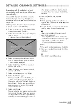
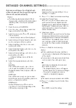
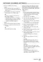
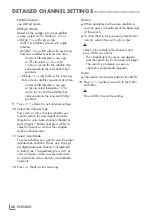
GENERAL OPERATING PRINCIPLE OF THE TV
-----------
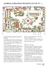
General Operating Principle of
Chassis
In products with a Gm chassis, the URSA circuit
in KY and KT chassis is not used as an external
circuit. It is found in the main integrated circuit
and is 50 HZ-supported. There will be no sup-
port for 100 HZ.
As seen in the block diagram the signals re-
ceived from all audio and video sources provide
input to main integrated circuit. Image is sent
to panel with LVDS lines from main integrated
circuit after it is processed. Likewise, the sound
is sent to the sound amplifier after being pro-
cessed.
While performing these processes, the main in-
tegrated circuit reads software installed on flash
and key data. There is not an SPI Flash where
boot software is stored or a system EEPROM
where key data is stored as in our previous
projects. All of these have been transferred into
the IC. This integrated circuit must be checked if
key data or boot software are considered faulty.
RAMs are used for the processes performed
within the integrated circuit.
Of course, the system should be supplied power
in 5 V, 3.3 V, 1.8 V, 1.5 V and 1.18 V which is
required for these processes.
DC Power Stage
Chassis and supply unit should be connected
via S100 connector. In GM-chassis products,
only 5V is fed from the supply unit (PSU) in
Stand-By mode (VCC_STB). The supply unit's 12
V, 12.5 V, 13.5 V and 24 V supplies for different
cabins and inches are activated through the con-
trol of the main integrated circuit when the TV is
exiting Stand-By mode. All of these voltages are
supplied from PSUs.
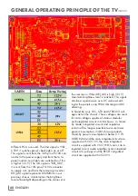
On S100 connector, 3 main control signals
are sent to the power supply. The first signal is
"POWER_SW"; it is sent to the power source
from 10th pin of S100 connector. The voltages it
activates in ON position are shown in the table.
Summary of Contents for COREMAX M1 PROJECT GM
Page 1: ...COREMAX M1 PROJECT GM CHASSIS SERVICE MANUAL...
Page 66: ...ENGLISH 66 GENERAL OPERATING PRINCIPLE OF THE TV Block Diagram...
Page 81: ...ENGLISH 81 CHASSIS DIAGRAMMATIC IMAGES Chassis DC Socket DC voltages...
Page 82: ...ENGLISH 82 CHASSIS DIAGRAMMATIC IMAGES...
Page 83: ...ENGLISH 83 CHASSIS DIAGRAMMATIC IMAGES Terrestrial tuner Satellite tuner...
Page 84: ...ENGLISH 84 CHASSIS DIAGRAMMATIC IMAGES USB...
Page 86: ...ENGLISH 86 FAILURE ERROR ANALYSES...
Page 88: ...ENGLISH 88 FAILURE ERROR ANALYSES...


