GROWSPAN
™
ROLLING PREMIUM HIGH TUNNELS
18
Revision date: 01.01.16
FRAME ASSEMBLY
Gather the parts:
• All Rafter Assemblies (End and Interior)
• Pipe 1.315'' x 75'' swaged (#131S075)
• Pipe 1.315'' x 73.5'' plain) – See Side Profile Diagrams
in Quick Start section for quantities.
• Castors attached to 30R1904D rafter sections
• Lifts, ladders, tools, and assistants
Frame Assembly Procedure
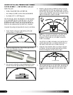
1. Using the proper lifts and with assistance, carefully
stand the first end rafter—one with end clamps—and
install the first set of end pipes with castors. Verify that
the rafter is set so that the 102857 end clamps are
positioned as shown below.
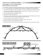
2. Center the castor on the track pipe and secure the
30R1904D pipe to the rafter using two (2) FA4482B Tek
screws.
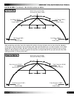
3. Verify rafter is plumb and brace it in place using cables,
ropes, or dimensional lumber. Leave bracing in place
until additional rafters and purlins are installed.
IMPORTANT:
Brace
the first rafter in
position as needed to
keep it from moving.
Bracing is removed
after
additional
rafters are installed
and secured to the
other rafters.
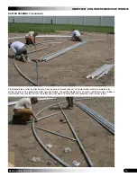
Photo shows the first end rafter and first interior rafter set
in place on the track pipe. End rafter is secured to the site
using one of the anchor stakes included with the building.
Crew members
install the short
30R1904D rafter
pipe with castor.
Before securing
the pipe to the
main rafter using
two FA4482B Tek
screws, verify
that the castor is
centered on the
track pipe.
NOTE:
Sample rafter above is used to illustrate
bracing. Actual rafter may differ in design, width or
both.
4. Place an interior rafter–one without end clamps—into
position and install the short pipe with castors (Steps 1
and 2) above.
To the
inside of
the shelter
End Rafter

