background image

Model G1015 (Mfg. since 7/99)

-21-

Sanding Belt

The Model G1015 accepts sanding belts that are 
2" wide and 72"–76" in length.

Note:  If you use the optional Model G9242  10" 
drive wheel, you need to use a sanding belt that 
is longer than the included 72" belt.

To  ensure  a  safe  operation  and  good  sand-
ing  results,  the  sanding  belt  must  be  properly 
installed, tensioned, and tracked.

Installing Sanding Belt

1.  DISCONNECT MACHINE FROM POWER!

2.  With the direction arrows printed on the inside 

front of the belt facing down, pull down on the 
quick release lever and wrap the belt around 
idler and drive wheels so that it is centered on 
both, as shown in 

Figure 18, then release the 

lever.


Note: To prevent the belt seam from catching 
on the workpiece, install the belt so that the 
direction arrows printed on the inside face of 
the belt follow the belt rotation, as shown in 

Figure 18.

3.  Adjust the platen so that it is centered behind 

the belt.

4.  If  needed  for  your  operation,  adjust  the  tool 

rest  position  as  required.  Make  sure  that  it 
is  no  more  than 

1

8

"  away  from  the  sanding 

belt  to  prevent  the  workpiece  being  trapped 
between the tool rest and belt.

Tensioning Sanding Belt

The sanding belt is properly tensioned when there 
is approximately 

1

2

" deflection with slight pressure 

applied to the back loop of the belt, as shown in 

Figure 19.

The sanding belt is adjusted by raising or lowering 
the sanding arm assembly.

Tools Needed 

Qty

Hex Wrench 

3

16

" ................................................ 1

To correctly tension the sanding belt:

1.  DISCONNECT MACHINE FROM POWER!

2.  Make  sure  the  sanding  belt  is  correctly 

installed and centered on the idler and drive 
wheels.

Figure 19. Checking the sanding belt tension.

If the sanding belt comes loose from the 

machine during operation, it could cause 

serious personal injury from entanglement 

or abrasion. ALWAYS make sure the sand-

ing belt is properly installed, tensioned, and 

tracked before connecting the machine to 

power.

Figure 18. Sanding belt installed.

Quick

Release

Lever

Tool

Rest

Sanding

Belt

Platen

Belt

Direction

Summary of Contents for G1015

Page 1: ...NING NO PORTION OF THIS MANUAL MAY BE REPRODUCED IN ANY SHAPE OR FORM WITHOUT THE WRITTEN APPROVAL OF GRIZZLY INDUSTRIAL INC FOR MODELS MANUFACTURED SINCE 7 99 TS11937 PRINTED IN TAIWAN MODEL G1015 KN...

Page 2: ...g grinding tool integrity and the usage of personal protective equipment The manufacturer will not be held liable for injury or property damage from negligence improper training machine modifications...

Page 3: ...ventory 11 Hardware Recognition Chart 12 Cleanup 13 Site Considerations 14 Mounting 15 Assembly 15 Test Run 18 SECTION 4 OPERATIONS 19 Operation Overview 19 Sanding Belt 20 Belt Sanding 22 Auxiliary A...

Page 4: ...machine We made every effort to be exact with the instruc tions specifications drawings and photographs in this manual Sometimes we make mistakes but our policy of continuous improvement also means th...

Page 5: ...dentification Belt Quick Release Lever Tracking Adjustment Knob Sanding Platen Drive Wheel Adjustable Tool Rest Tilting Sanding Arm Push Pull ON OFF Button Idler Wheel Auxiliary Arbor To reduce your r...

Page 6: ...t 38 3 4 x 29 1 2 x 39 in Foot Print Length Width 10 x 16 1 4 in Shipping Dimensions Carton 1 Type Cardboard Content Machine Weight 58 lbs Length Width Height 31 x 17 x 15 in Carton 2 Type Cardboard C...

Page 7: ...with R Drive Roller Length 7 in Drive Wheel Diameter 8 in Idler Roller Type Aluminum Idler Roller Length 2 in Idler Roller Diameter 4 in Spindle Info Spindle Speed 1750 RPM Arbor Size 5 8 in Total Ar...

Page 8: ...roof DANGEROUS ENVIRONMENTS Do not use machinery in areas that are wet cluttered or have poor lighting Operating machinery in these areas greatly increases the risk of accidents and injury MENTAL ALER...

Page 9: ...oving parts or flying debris Make sure they are properly installed undamaged and working correctly BEFORE operating machine FORCING MACHINERY Do not force machine It will do the job safer and better a...

Page 10: ...rkpieces can result in loss of control resulting in abrasion injuries impact injuries or damage to sandpaper Only sand solid workpieces that can withstand power sanding forces Make sure workpiece shap...

Page 11: ...the risk of these hazards avoid over loading the machine during operation and make sure it is connected to a power supply circuit that meets the specified circuit requirements For your own safety and...

Page 12: ...rd size gets longer and the gauge size gets smaller higher gauge numbers indicate smaller sizes Any extension cord used with this machine must be in good condition and contain a ground wire and matchi...

Page 13: ...and all packing materials for possible inspection by the carrier or its agent Otherwise filing a freight claim can be difficult When you are completely satisfied with the condi tion of your shipment i...

Page 14: ...embly 1 P Tool Rest 1 Q Platen Bracket 1 R Sanding Platen 1 Figure 3 Model G1015 inventory A B C D E F G H I J K L M O N P Q R The following is a list of items shipped with your machine Before beginni...

Page 15: ...Model G1015 Mfg since 7 99 13 5mm Hardware Recognition Chart...

Page 16: ...er optional Basic steps for removing rust preventative 1 Put on safety glasses 2 Coat the rust preventative with a liberal amount of cleaner degreaser then let it soak for 5 10 minutes 3 Wipe off the...

Page 17: ...ironment The physical environment where the machine is operated is important for safe operation and lon gevity of machine components For best results operate this machine in a dry environment that is...

Page 18: ...shers and hex nuts are used to secure the machine to the workbench Machine Base Workbench Hex Bolt Flat Washer Flat Washer Lock Washer Hex Nut Figure 6 Example of a through mount setup Machine Base Wo...

Page 19: ...ing surface and use the eight holes in the base of the motor assembly and the arm bracket assembly as a template for drilling the mount ing holes 7 Loosen the three cap screws of the pivot arm bracket...

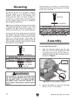
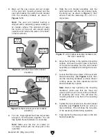
Page 20: ...he pre installed hardware as shown in Figure 15 10 Back out the two set screws in the round housing of the pivot arm slide the arm onto the bracket bushing so that the platen bracket cap screws are fa...

Page 21: ...n the rest and belt during operation Test Run Once the assembly is complete test run your machine to make sure it runs properly If during the test run you cannot easily locate the source of an unusual...

Page 22: ...nects the machine to power and pulls the ON OFF button out to turn it ON 7 Verifies that the sanding belt is tracking prop erly and rotating without interference 8 Places the workpiece onto the tool r...

Page 23: ...entered behind the belt 4 If needed for your operation adjust the tool rest position as required Make sure that it is no more than 1 8 away from the sanding belt to prevent the workpiece being trapped...

Page 24: ...oned 3 Rotate the drive wheel several times by hand and watch the sanding belt as it tracks on the idler and drive wheels If the sanding belt is centered on the idler and drive wheels and does not mov...

Page 25: ...lent surface for angular sanding or polishing Figure 22 shows a typical wood sanding opera tion with the tool rest perpendicular to the belt surface Figure 22 Typical wood sanding operation The sandin...

Page 26: ...se you will need to mount it differently so that it will not interfere with the sanding belt 5 Check and adjust if necessary the sanding belt tracking refer to Adjusting Sanding Belt Tracking on Page...

Page 27: ...ton that s been treated to stiffen the material Pleats help hold compound Perfect for removing light scratches in a variety of metals H4697 6 D x 5 8 Bore H1388 8 D x 5 8 Bore Figure 31 Spiral sewn bu...

Page 28: ...grime with a dry cloth If any resin has built up use a resin dissolv ing cleaner to remove it Treat all unpainted cast iron and steel with a non staining lubricant after cleaning Cleaning Lubrication...

Page 29: ...fault 8 Motor at fault 1 Ease the workpiece into the sanding belt or attachment with light pressure 2 Wire motor correctly Page 29 3 Test for good contacts correct wiring 4 Test repair replace 5 Use n...

Page 30: ...on platen worn out 4 Idler wheel bearing worn out 1 Adjust upper wheel guard correctly adjust belt tracking Page 21 2 Adjust tool rest away from belt no more than 1 8 3 Replace platen 4 Replace beari...

Page 31: ...k all wires dis connected or connected during any wiring task to ensure tight connections CIRCUIT REQUIREMENTS You MUST follow the requirements at the beginning of this manual when connecting your mac...

Page 32: ...Mfg since 7 99 READ ELECTRICAL SAFETY ON PAGE 28 Wiring Diagram wiring diagram Motor ON OFF Button Ground 110V NEMA 5 15 Plug As Recommended Ground Hot Neutral Start Capacitor 400M 125V Figure 33 Ele...

Page 33: ...15006 STATOR WINDING 21 P1015021 PHLP HD SCR 10 24 X 1 2 7 P1015007 CONTACT PLT LG INT PT 22 P1015022 S CAPACITOR 400M 125V 1 3 4 X 3 3 8 8 P1015008 LOCK WASHER 3 16 23 P1015023 CAPACITOR COVER 9 P101...

Page 34: ...80 86 83 75A 37 36A 33C Mfg Since 7 99 33B Mfg 12 95 6 99 37 81 81 74 76 76 81 42A 41A 40 39A 82 73 30 84 32A 34 81 81 34 35 35 52A 54 53A 46A 51 47 68 66 50 65 57 56A 62A 63 43 44 51 48 55A 59 49 58...

Page 35: ...1 PCAP04 CAP SCREW 1 4 20 X 1 2 42A PCAP35 CAP SCREW 1 4 28 x 5 8 72 P1015072 IDLER WHEEL 43 P1015043 COMPRESSION SPRING D22 3 X 87MM 73 P1015073 DRIVE WHEEL 44 P1015044 UPPER SHAFT BRACKET 74 P101507...

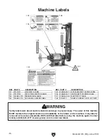
Page 36: ...or becomes unreadable REPLACE that label before using the machine again Contact Grizzly at 800 523 4777 or www grizzly com to order new labels REF PART DESCRIPTION REF PART DESCRIPTION 101 P1015101 MA...

Page 37: ...metalworker ____ 0 2 Years ____ 2 8 Years ____ 8 20 Years ____20 Years 6 How many of your machines or tools are Grizzly ____ 0 2 ____ 3 5 ____ 6 9 ____10 7 Do you think your machine represents a good...

Page 38: ...LINE FOLD ALONG DOTTED LINE GRIZZLY INDUSTRIAL INC P O BOX 2069 BELLINGHAM WA 98227 2069 Place Stamp Here Name_______________________________ Street_______________________________ City______________S...

Page 39: ...shall be tried in the State of Washington County of Whatcom We shall in no event be liable for death injuries to persons or property or for incidental contingent special or consequential damages arisi...

Page 40: ......

Reviews: