-62-
Model G0827 (Mfd. Since 11/17)
2. Loosen four locking set screws.
3. Loosen four jam nuts on adjusting set screws,
and back out set screws two full turns. The
gibs should now be free and loose.
4. Tighten adjusting set screws for each gib
alternately until both gibs are just touch-
ing dovetail way along their full length; then
tighten locking set screws and jam nuts.
5. Test gib adjustment by moving knee up and
down.
6. Repeat Steps 2–5 as necessary until you are
satisfied.
Note:
Adjusting parameters for these gibs
are same for other gibs earlier in this sec-
tion—just snug enough to cause slight drag.
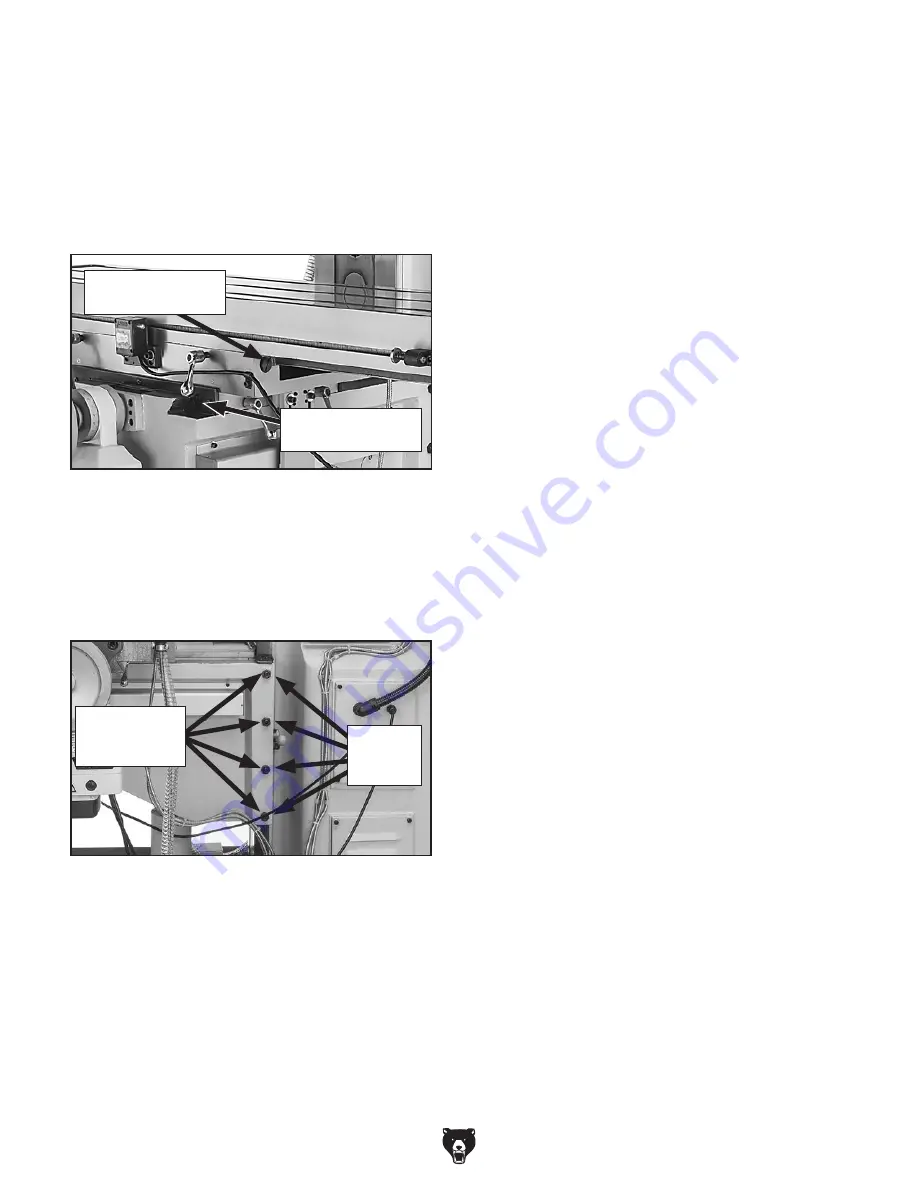
Figure 100. Locations of X- and Y-axis gib
adjustment screws.
X-Axis Gib Screw
(1 of 2)
Y-Axis Gib Screw
(1 of 2)
Adjusting Z-Axis Gibs
1. Locate four locking and four adjusting set
screws for the two column gibs on right side
of knee (see
Figure 101).
Figure 101. Z-axis gib set screws (shown from
right side of knee way).
Adjusting
Set Screws
and Jam Nuts
Locking
Set
Screws
Adjusting X- & Y-Axis Gibs
1. Make sure all table locks are loose.
2. Loosen one gib adjustment screw
(see
Figure 100) and tighten opposite screw
same amount to move gib, while at same
time rotating handwheel to move table until
you feel slight drag in that path of movement.
Summary of Contents for G0827
Page 92: ......


