


Model G0692 (Mfg. 11/08 and Later)
-29-
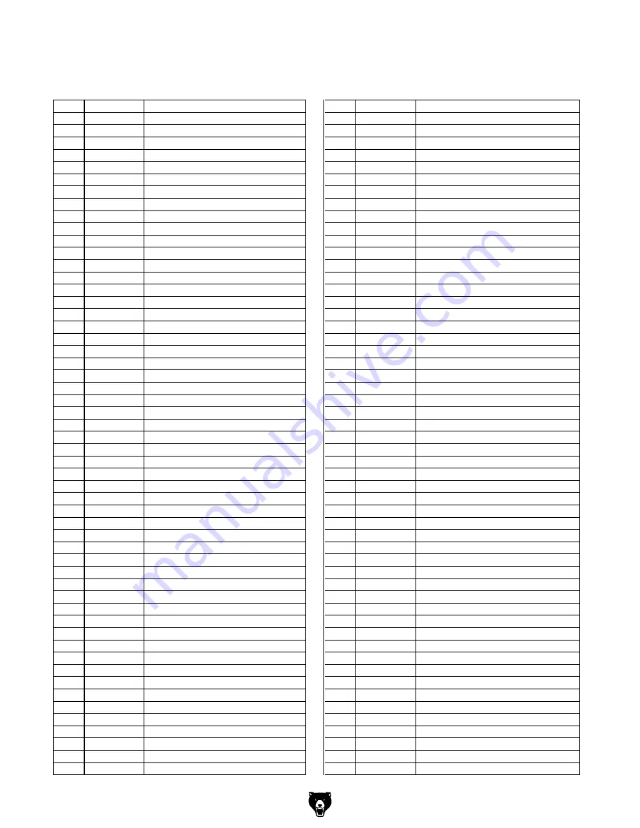
parts List
REF
PART #
DESCRIPTION
REF
PART #
DESCRIPTION
1
P0692001
BASE
56
P0692056
BEARING BUSHING
2
P0692002
ANCHOR HOUSING
57
P6000LLB
BALL BEARING 6000LLB
3
PSB40M
CAP SCREW M8-1.25 X 35
58
PW03M
FLAT WASHER 6MM
4
PLW04M
LOCK WASHER 8MM
59
PLW03M
LOCK WASHER 6MM
5
P0692005
VISE SLIDE PLATE
60
PSB02M
CAP SCREW M6-1 X 20
6
P0692006
MOTOR TILT BASE
61
P0692061
RUBBER SEAT
7
P6202LLB
BALL BEARING 6202LLB
62
PSB26M
CAP SCREW M6-1 X 12
8
P0692008
ROTOR
63
P0692063
CENTER COVER
9
P6000LLB
BALL BEARING 6000LLB
64
P6000LLB
BALL BEARING 6000LLB
10
P0692010
AIR FLOW COVER
65
PSB33M
CAP SCREW M5-.8 X 12
11
P0692011
MOTOR FRAME
66
P0692066
SLIDING GUARD ASSEMBLY
12
P0692012
BRUSH HOLDER
67
P0692067
CONNECTION ROD ASSEMBLY
13
PW05M
FLAT WASHER 4MM
68
P0692068
SPECIAL CAP SCREW M5-.8 X 12
14
PHTEK31M
TAP SCREW M4 X 14
69
P0692069
GUARD BUSHING
15
P0692015
STATOR
70
PW01M
FLAT WASHER 8MM
16
PTLW02M
EXT TOOTH WASHER 5MM
71
P0692071
CONNECTION ROD BUSHING
17
PHTEK43M
TAP SCREW M5 X 70
72
PB84M
HEX BOLT M8-1.25 X 14
18
PW02M
FLAT WASHER 5MM
73
P0692073
LOCK LEVER
19
PLW01M
LOCK WASHER 5MM
74
P0692074
RUBBER RING
20
P0692020
CAP SCREW M5-.8 X 28
75
P0692075
KNOB HANDLE
21
P0692021
CARBON BRUSH SET
76
PR04M
EXT RETAINING RING 6MM
22
P0692022
COVER
77
P0692077
SHAFT
23
PW05M
FLAT WASHER 4MM
78
PSB04M
CAP SCREW M6-1 X 10
24
PHTEK6M
TAP SCREW M4 X 16
79
P0692079
SPRING SEAT SHAFT
25
P0692025
GEAR SHAFT
80
P0692080
SPRING RUBBER SEAT
26
PK19M
KEY 5 X 5 X 14
81
P0692081
COMPRESSION SPRING
27
P0692027
PINION M1.25 X 43T
82
PN03M
HEX NUT M8-1.25
28
PEC03M
E-CLIP 10MM
83
PB126M
HEX BOLT M8-1.25 X 40
29
P6000LLB
BALL BEARING 6000LLB
84
P0692084
ARBOR FLANGE
30
P0692030
ARBOR
85
T20920
BLADE 58-T 350 X 2.4 X 25.4MM
31
P6205LLB
BALL BEARING 6205LLB
86
P0692086
CLAMP WASHER
32
P0692032
GEAR M1.5 X 40T
87
PB56M
CAP SCREW M10-1.5 X 20
33
PK14M
KEY 5 X 5 X 18
88
P0692088
PIVOT SHAFT
34
PEC03M
E-CLIP 25MM
89
P0692089
FIXED VISE JAW
35
P6200LLB
BALL BEARING 6200LLB
90
P0692090
ANGLE SCALE
36
P0692036
GEAR BOX
91
P0692091
DISC SPRING
37
P0692037
LOWER SWITCH HANDLE
92
P0692092
BUSHING
38
PW05M
FLAT WASHER 4MM
93
P0692093
PULL BAR
39
PHTEK28M
TAP SCREW M4 X 25
94
PSB26M
CAP SCREW M6-1 X 12
40
P0692040
TRIGGER SWITCH
95
P0692095
T-NUT M8-1.25
41
PW05M
FLAT WASHER 4MM
96
P0692096
SPACER RING
42
PHTEK39M
TAP SCREW M4 X 12
97
P0692097
STUD
43
P0692043
WIRE RETAINER
98
P0692098
LEVER
44
P0692044
UPPER SWITCH HANDLE
99
PFH02M
FLAT HD SCR M6-1 X 12
45
PHTEK42M
TAP SCREW M4 X 35
100
P0692100
SADDLE
46
P0692046
WIRE GUARD
101
P0692101
COMPRESSION SPRING
47
P0692047
POWER CORD 110V 8'
102
P0692102
STEEL BALL
48
P0692048
RIGHT SIDE HANDLE
103
P0692103
LEADSCREW ASSEMBLY
49
P0692049
LEFT SIDE HANDLE
104
PN02M
HEX NUT M10-1.5
50
P6000LLB
BALL BEARING 6000LLB
105
PW04M
FLAT WASHER 10MM
51
P0692051
GUARD TUBE
106
P0692106
SLAG TRAY SLIDE
52
P0692052
FRONT SHAFT BRAKE LEVER
107
PSB23M
CAP SCREW M4-.7 X 12
53
P0692053
COMPRESSION SPRING
108
PLW02M
LOCK WASHER 4MM
54
P0692054
SAWBLADE GUARD
109
P0692109
SLAG TRAY
55
PSB137M
CAP SCREW M5-.8 X 55
110
PW02M
FLAT WASHER 5MM
Summary of Contents for G0692
Page 36: ......