


-70-
Model g0661/g0713 (Mfg. since 1/10)
3. With the end of the adjustable square just
touching the tip, lock the square in place.
now, mark the carbide tip with a marker
where you made this measurement.
4. rotate the marked blade tip to the other end
of the table insert.
5. slide the adjustable square down to the other
end of the table insert, and compare the dis-
tance from the marked blade tip to the end of
the adjustable square.
—
if the blade tip does not touch the end of
the adjustable square similar to the first
measurement, the table will need to be
adjusted. proceed to
Step 6.
—if the blade tip measurement is the same
on both sides, go to
Step 7.
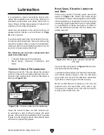
6. to adjust the table, loosen the hex bolts in
the table mounting locations (see
Figure
113) and slightly tap the table in the needed
direction. repeat
Steps 2–5 until the blade
and miter slot are parallel.
7. tighten the table mounting bolts in a criss-
cross, alternating manner.
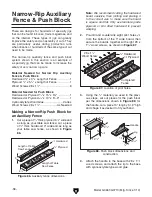
The saw blade is sharp. use extra care or
wear gloves when handling the blade or
working near it.
Figure 113. table mounting bolts.
table Mounting Bolts
(2 of 6)
Spreader or Riving
Knife Alignment
Checking Alignment
the blade guard spreader and riving knife must
be aligned with the blade when installed. if the
spreader/riving knife is not aligned with the blade,
then the workpiece will before forced sideways
during the cut, which will increase the risk of kick-
back.
Tools Needed
Qty
straightedge ...................................................... 1
To check the spreader/riving knife alignment:
1. disConnECt saW FroM poWEr!
2. raise the saw blade to the maximum height
so you have easy working access.
3. Check to make sure the blade is 90° to the
table. Follow "setting 90° stop Bolt" instruc-
tions on
page 68.
4. place the straightedge against the top and
bottom of blade and spreader/riving knife,
as shown in
Figure 114. the spreader/riv-
ing knife should be be parallel with the blade
along its length at both positions and should
be in the "alignment zone," as shown in
Figure 115.
Figure 114. Checking top and bottom riving knife
parallelism with blade.
IVWaZ
G^k^c\
@c^[Z
Ide6a^\cbZci
7diidb6a^\cbZci


