Frankenrunner User Manual
Rev 1.0
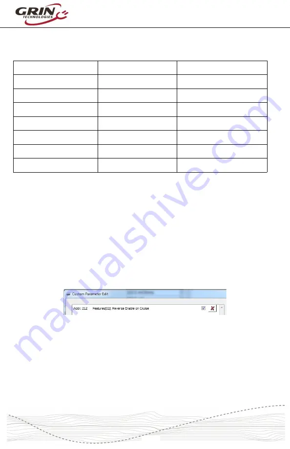
These settings can be seen by going edit->edit parameters as shown above. The
difference between the V3 Phaserunner devices and
Frankenrunner
are
summarized in the table below:
Input Source
Phaserunner (V3)
Frankenrunner
Throttle Source
Analog Input 1 (Thrt)
Analog Input 2 (Brk1)
Regen Brake Source
Analog Input 3 (Brk2) Analog Input 2 (Brk1)
Torque Sensor Source
N/A
Analog Input 1 (Thrt)
Motor Temperature
N/A
Analog Input 4 (BMS)
PAS
N/A
Digital Input 2 (PFS)
Wheel Speed Sensor
Hall A
Analog Input 3 (Brk2)
Fwd/Rev
Digital Input 1 (Cruise) Digital Input 1 (Cruise)
These changes were necessary to fully support the independent use of torque
sensors and throttles on the same controller. As a result if full parameter settings
saved from a Phaserunner device are then imported to the
Frankenrunner
or vice
versa, unexpected throttle and braking behavior can occur.
6.2 Reverse Mode
The signal
PAS 2
used in the 6 pin PAS plug is electrically equivalent to the
FWD/REV
pin in the Main plug. This input is by default configured as a reverse
switch input by enabling “Reverse on Cruise” for applications that require
direction reversal. When using quadrature (2 wire) PAS sensors plugged into the
PAS plug, this must be unchecked.
6.3 Wheel Speed Sensing
The
Frankenrunner
will automatically select the source of the wheel speed signal
for vehicle speed measurement. If there are speed pulses present on the wheel
speed sensor pin then these will be mapped automatically to the Cycle Analyst
plug. If no speed pulses are detected even after the motor is spinning, then the
motor Hall signals will get fed to the speed signal input instead.
-20-


