background image


Greenline 33                   


68


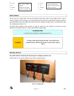
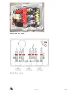
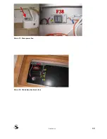
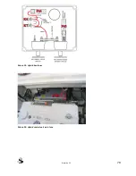
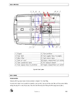
Picture 15: Mooring box fuses 


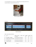
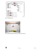
Picture 16: Mooring box (located under the bed in the cabin); anchor winch fuse 


Summary of Contents for GREENLINE 33

Page 1: ...OWNER S MANUAL GREENLINE 33 Revision 04 19 03 2012...

Page 2: ...Greenline 33 II...

Page 3: ...INST FIRE EMERGENCY EXITS 22 BILGE STRIPPING 26 EMERGENCY CONTROL 28 4 HULL 29 THROUGH HULL FITTINGS 29 SEACOCK 30 HULL MAINTENANCE 30 DRY DOCKING 31 GEL COAT REPAIRS INSTRUCTION 31 5 DECK 33 DECK LAY...

Page 4: ...ILATION SYSTEM 79 DETERMINATION OF MAXIMUM PROPULSION POWER RATING 79 DASH BOARD CONTROL LEVER 79 VISIBILITY IN THE STEERING STATION 80 PROPELLERS 81 ANODE 81 FUEL SYSTEM 82 FUEL TANK 82 FUEL FILTER 8...

Page 5: ...osition for emergency tiller 28 Figure 16 Thru hull fitting positions 29 Figure 17 Deck layout 33 Figure 18 Anchor winch with chain stopper 35 Figure 19 Manual switch for el platform 37 Figure 20 Latc...

Page 6: ...Greenline 33 VI Figure 38 Position of hoisting cradle and straps 88...

Page 7: ...Picture 10 48V main hybrid switch 62 Picture 11 Location of AC DC panel 63 Picture 12 AC DC panel 63 Picture 13 Main 12V power box 67 Picture 14 Service box fuses 67 Picture 15 Mooring box fuses 68 Pi...

Page 8: ...f the craft shall be assessed executed and documented by competent people The boat builder cannot be held responsible for modifications he has not approved In some countries a driving licence or autho...

Page 9: ...ather conditions the sea condition and that only an experienced and very fit crew handling a well maintained boat can sail satisfactorily The sea and wind conditions that correspond to the design cate...

Page 10: ...der in particular as for the total weight of the food supplies of the different equipments that are not supplied by the builder and the weight of the persons on board and this load must be properly di...

Page 11: ...at DWL excluding antenna HA m 3 10 Displacement volume displacement at DWL VD kg 5700 light craft condition mass LCC mLCC kg 5100 minimum operation condition MOC mMCC kg 5310 loaded craft mass LDC mL...

Page 12: ...engers Crew crew passengers 8 Certification EU RCD category B Offshore General specifications ISO8666 The engine is the main propulsion means of the GREENLINE 33 Boat builder SEAWAY YACHTS RC NMPT d o...

Page 13: ...Greenline 33 6 Figure 1 Boat main dimensions...

Page 14: ...ts used for professional purposes as charter fishing work boats etc 2 Warranty on parts that deteriorate rapidly due to wear and tear including but not limited to 12 V batteries external decorations c...

Page 15: ...h were modified or repaired even partially by a shop not authorized by the Builder 5 damages resulting from non observance of maintenance recommendations as described in the Owner s Manual submitted w...

Page 16: ...Greenline 33 9 Figure 2 Boat examination report...

Page 17: ...Greenline 33 10 Figure 3 Engine examination certificate VW SDI 75 5...

Page 18: ...Greenline 33 11 Figure 4 Engine examination certificate VW TDI 165 5...

Page 19: ...Greenline 33 12 Figure 5 Declaration of Conformity...

Page 20: ...Greenline 33 13...

Page 21: ...o maintain design trim approximately level Avoid placing heavy weights high up DEFINITION OF THE DESIGN CATEGORIES CATEGORY B A boat given design category B is considered to be designed to operate in...

Page 22: ...DRESS HULL NUMBER CIN CODE REGISTRATION NUMBER ENTRANCE KEY NUMBER ENGINE TYPE ENGINE SERIAL NUMBER GEARBOX SERIAL NUMBER HYBRID DRIVE SERIAL NUMBER ENGINE KEY NUMBER DATE OF DELIVERY COMMISSIONING DI...

Page 23: ...Greenline 33 16 3 SAFETY LIFE RAFT STORAGE 1 Swim m ing ladder m eans of com m ing back onboard 2 Position of the liferaft not supplied 1 2 Figure 7 Liferaft storage location...

Page 24: ...on the raft and should be read carefully before putting to sea WARNING Check the safety equipments inventory before each trip RECOMENDATION We advise you to close the deck hatches and portholes befor...

Page 25: ...Greenline 33 18 MAN OVERBOARD PREVENTION AND RECOVERY Figure 8 Working deck area plan...

Page 26: ...Greenline 33 19 LPG SYSTEM 2 1 4 3 5 5 G as cylinder valve 6 C ooker oven 1 G as cylinder 2 3 4 G as hose G as circuit valve Ventilated gas cylinder com partm ent Figure 9 LPG system plan...

Page 27: ...ces burns oxygen in the cabin and releases combustion gases therefore ventilation is mandatory when the appliances are used Don t obstruct the ventilation holes and at least leave the door open Don t...

Page 28: ...deterioration or openings are found Do not use the stove when high angles of rolling or sustained angles of heel are likely if the craft is not equipped with a gimballed stove Always apply to an exper...

Page 29: ...Greenline 33 22 FIGHT AGAINST FIRE EMERGENCY EXITS Figure 10 Fire extinguishers positions Emergency exits...

Page 30: ...nd shut the fuel supply and close engine room ventilation Inject the extinguishing agent through the aperture or activate fixed fire Extinguisher if installed Wait a minute Open the access hatch for a...

Page 31: ...liances with an open flame The combustible products shall not be stored in the engine compartment If you store non combustible products in the engine compartment they shall be fastened so that they ca...

Page 32: ...tion or having equivalent technical and fire resistant capabilities Do not fit free hanging curtains or other fabrics in the vicinity of or above cookers or other open flame devices Do not stow combus...

Page 33: ...of the bilge pump is 126 l min Figure 12 Automatic bilge pump with automatic switch EMERGENCY BILGE PUMP The control arm of manual bilge pump is located in the port side of the cockpit The control ar...

Page 34: ...Greenline 33 27 Figure 14 Bilge pump system plan...

Page 35: ...all be kept closed and shall only be opened to let water drain into the main bilges WARNING The combined capacity of the system is not intended to drain the craft in the case of hull damage EMERGENCY...

Page 36: ...Greenline 33 29 4 HULL THROUGH HULL FITTINGS Figure 16 Thru hull fitting positions...

Page 37: ...nance will be required to protect your boat from outside attacks sun salt electrolysis Use small amount of cleaner and do not reject them in the sea Try to wash your boat on shore Do not use any solve...

Page 38: ...e exhaust In that case the engines would be damaged and out of guarantee The load limit is determined by a maximum sinking that can be measured when in the marina Full tanks and no crew onboard GEL CO...

Page 39: ...case of contact wash with soapy water and rinse liberally GEL COAT STORAGE Get coat components must be stored in a cool place protected from moisture and light for maximum 6 months to ensure adequate...

Page 40: ...Greenline 33 33 5 DECK DECK LAYOUT 1 1 1 1 1 3 2 2 1 M ooring cleat 2 3 Swim m ladder Towing Figure 17 Deck layout...

Page 41: ...rotect the boat with suitably sized fenders Always keep the ropes unfolded and home Handle the boat at slow speed DANGER Never try to stop the boat with your foot your hand or a boat hook When taut Pr...

Page 42: ...the chain or cable from the cable lifter Secure the chain on the cleat RECOMENDATION Don t use the cable lifter to secure the chain HEAVING UP ANCHOR Lock the windlass snubber Ensure that the chain i...

Page 43: ...ions are dangerous therefore the anchor line shall always be clear and free Always proceed with care and using gloves RECOMENDATION After every trip rinse the windlass and anchor chain with fresh wate...

Page 44: ...form Make sure the rope is not too tight max 200N Close the latch on the both sides after closing the platform Figure 19 Manual switch for el platform Figure 20 Latch on the platform WARNING When usin...

Page 45: ...ater Polish with shammy leather OUTSIDE MASSIVE WOOD Regularly rinse woodworks with freshwater and scrub with soft brush Dress massive wood with fine sand paper to restore its colour Minor deck damage...

Page 46: ...tect the inside of your boat from UV rays Bred crumps must be systematically eliminated Ensure that the bilges are cleaned and dry INSIDE VARNISH Rinse inside varnish with degreasing shampoo mixed wit...

Page 47: ...thout rubbing with a white spirit soaked cloth RECOMENDATION For PVC fabrics Solvents or solvent based products pure alcohol acetone and trichloroethylene are strictly prohibited 100 polyester Jackard...

Page 48: ...Greenline 33 41 7 PLUMBING Sea water plumbing Figure 22 Sea water plumbing...

Page 49: ...Greenline 33 42 Freshwater plumbing Figure 23 Fresh water plumbing...

Page 50: ...Greenline 33 43 Grey water plumbing Figure 24 Grey water plumbing...

Page 51: ...istakes never fill the water and fuel tanks at the same time During filling avoid handling contaminants near the filling plugs Open and close the filling plugs with the special key or winch handle Che...

Page 52: ...from pharmacies Purify the tanks and pipes with acetic acid or white vinegar if the boat is to stay unmanned for a long period Inspection ports are provided on tanks through which internal cleaning c...

Page 53: ...tory with antifreeze in water system Consumption of antifreeze may cause illness death System must be thoroughly flushed several times to remove antifreeze before use TOILET OPERATION CAUTION Please d...

Page 54: ...osets is discharged by sea chests fitted with quarter turn valves when the valve handle is perpendicular with the pipe the valve is closed and open when along the pipe centreline Water from the floor...

Page 55: ...e the pump To empty the bowl set the pump lever back to DRY and actuate the pump Use exclusively absorbent biodegradable paper to avoid clogging the heads and rinse the system regularly with fresh wat...

Page 56: ...the propulsion switches you can switch them ON before departure B STAYING AT DOCK OR ANCHOR A B GETTING READY TO SAIL 12 V SERVICE battery switch Pic 1 48V HYBRID HOUSE battery switch Pic 2 24h CONSUM...

Page 57: ...reenline 33 50 Picture 2 HYBRID DRIVE and HYBRID HOUSE main battery switch Picture 3 BOWTHRUSTER optional switch in the cabin Picture 4 24h CONSUMERS on the right side 230Vac CONSUMERS on the left sid...

Page 58: ...Greenline 33 51 Picture 5 INVERTER switch Phoenix multi control on the dashboard...

Page 59: ...ld appear on the VW control display if not check the position of the throttle lever Turn the DIESEL engine key to the START position to start the engine Ready to sail Switching the Diesel drive OFF Tu...

Page 60: ...ne key to the OFF 2 HYBRID switch to DIESEL 3 diesel engine key to the ON 4 diesel engine key to the START 5 ready to sail in DIESEL mode Electro Diesel 1 throttle lever in NEUTRAL 2 HYBRID switch to...

Page 61: ...error occurrs in hybrid system the third line is displayed Below the display there is a LED and when the hybrid system works properly the LED is green If malfunction occurs somewhere in the hybrid sys...

Page 62: ...and audible alarm over and under voltage During an alarm the buzzer will sound The alarm buzzer can be silenced by pressing any button For switching between the data screens press or For detailed info...

Page 63: ...the 48Vdc 230Vac inverter charger You can choose between ON charger ON 230V output ON and CHARGER ONLY charger ON no 230V output Picture 6 Phoenix multi control SAILING WITH DIESEL ENGINE In GENERATO...

Page 64: ...attery charger to charge 12V batteries also fuses F39 F40 turned ON From 12V batteries important consumers are supplied which are necessary for sailing hybrid cooling pump instruments navigation light...

Page 65: ...so recommended that the 230V fuse for the 12V battery charger is turned on so that all 12V batteries are being charged CAUTION When using 230V on board you should take care of the consumption of elect...

Page 66: ...ry voltage Charge the battery The internal temperature is reaching a critical level The inverter has switched off due to the electronics temperature being too high The inverter switched off due to exc...

Page 67: ...ls and on shadows of masts in marina and radar mast when sailing RECOMENDATION To keep the best performance keep solar panels clean WARNING Cleaning of solar panels is dangerous task It must be done b...

Page 68: ...There are 3 main electrical wirings on the boat For hybrid system the voltage is 48V For instruments lightning bowthruster etc there is 12V wiring For regural house consumers there is 230V AC wiring S...

Page 69: ...ch Picture 10 48V main hybrid switch FUSES Main AC DC panel is located in the saloon locker near the portside sofa Notice that these switches are automatic fuses at the same time Before leaving the bo...

Page 70: ...DC panel Picture 12 AC DC panel Table 2 Fuses and relays full option Fuse Power supply wiring path description Voltage V Rating A Typ e F1 Cabin lights salon lights From service bat via S3 via F32 12...

Page 71: ...S1 via F27 12 35 ANL F27 Engine battery Main engine battery fuse 12 355 ANL F28 Diode splitter From diode splitter to engine battery 12 125 ANL F29 Diode splitter From diode splitter to service batter...

Page 72: ...eater controls From service bat directly via F30 12 5 ATO F50 Defroster From service bat via S3 via F32 12 30 ATO K3 Hybrid cooling pump From F21 control from engine key switch 201 12 30 Relay K4 Engi...

Page 73: ...Greenline 33 66 FUSES LOCATION Hybrid box fuses LiPo battery bank main fuse Main 12V power box Shore power cable and fuse Service box fuses Mooring box fuses...

Page 74: ...Greenline 33 67 Picture 13 Main 12V power box Picture 14 Service box fuses...

Page 75: ...Greenline 33 68 Picture 15 Mooring box fuses Picture 16 Mooring box located under the bed in the cabin anchor winch fuse...

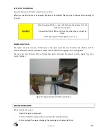
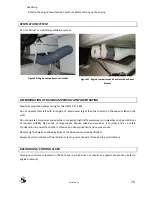
Page 76: ...Greenline 33 69 Picture 17 Shore power fuse Picture 18 LiPo battery bank main fuse...

Page 77: ...Greenline 33 70 Picture 19 Hybrid box fuses Picture 20 Hybrid control unit main fuse...

Page 78: ...ole 230Vac power source 230V circuit is powered from shore cable through Multiplus inverter charger hybrid only or directly standard When shore cable is not connected Multiplus goes to inverter mode h...

Page 79: ...microwave oven CAUTION When using 230V power you have to turn ON fuses F38 F42 see table 2 Fuse F41 water heater is also a switch Turn F41 OFF if you are not using water heater Maximal power consumpti...

Page 80: ...F38 under cockpit seat stbd side WARNING Disconnect shore power connection when the system is not in use Do not allow the shore power cable end to hang in the water An electrical field can be caused...

Page 81: ...LiPo battery bank is charged from the Victron Multiplus inverter charger shore cable connected inverter ON switch S6 ON or from hybrid generator when sailing in diesel mode Use your battery charger wh...

Page 82: ...y the rated current amperage of over current protective devices install or replace electrical appliances or devices with components exceeding the rated current amperage of the circuit leave the craft...

Page 83: ...nnect shore power see shore power chapter Turn OFF fuse F38 and F39 Turn OFF F11 cockpit lights You can also turn OFF diesel heater F20 make sure that it is cooled before turning OFF In water leave F1...

Page 84: ...r to the brochure supplied with the boat You must read carefully the brochure which includes detailed hints about the engine operation and how to run it properly Figure 28 Engine with Hybrid drive CAU...

Page 85: ...p etc ENGINE SEA VALVE The engine sea valve ensures a critical duty in the engine operation and therefore the strainer must be brushed whenever the ship is docked and kept clean and free from clogging...

Page 86: ...d on the capacity label in the craft Do not operate at maximum speed while in congested high traffic waterways or in weather and sea conditions of reduced visibility high winds or large waves Reduce s...

Page 87: ...l Regulations for preventing Collisions at sea COLREGS and the rules of the road require that a proper lookout be maintained at all times and observance of right way observance of these rules is essen...

Page 88: ...without specialist s advice ANODE RECOMENDATION Check regularly the anode on the transom and on the drive for corrosion and renew as required Check and replace the hydro lube oil ring if necessary REC...

Page 89: ...h the general precautions indicated in chapter 7 for tank filling To protect the deck from possible fuel splashes wet up the area around the deck filler with sea water before taking the plug off In ca...

Page 90: ...t before an extended unattended period Ensure that the tank is full to avoid condensation Clean the tank every five years to remove sludge deposits Every year check the condition of the fuel system tu...

Page 91: ...find out the filter renewal frequency and maintenance work The other one is a first stage filter located in the pipe system between the engine and the fuel tank Undo but do not remove the knurled scre...

Page 92: ...piston Rudder bearing 3 1 2 4 5 Section view A A Section view B B Scale 2 1 A B B A Figure 37 Steering system Regularly check the tightness of steering system components Regularly lubricate all the e...

Page 93: ...Greenline 33 86 In case of steering mechanism failure mount emergency steering tiller directly on rudder shaft...

Page 94: ...and a line aft and fenders as necessary Before hoisting ensure that the belts will not crush the locks speedometers shafts etc To that effect mark the belt position adhesive tape on the moulding for h...

Page 95: ...Greenline 33 88 PO SITIO N O F HO ISTING C RADLE AND STRAPS Figure 38 Position of hoisting cradle and straps...

Page 96: ...and leave all doors open cabins lockers wardrobes iceboxes Leave the cushions in the outside for a long time and re install in the boat in upright position to limit contact surfaces OUTSIDE Rinse libe...

Page 97: ...boat batteries Turn OFF all main switches S1 S6 Disconnect shore power see shore power chapter Turn OFF fuse F38 and F39 Turn OFF F11 cockpit lights You can also turn OFF radio memory F19 you will loo...

Page 98: ...tructions bellow in correct order 1 8 For mounting the LiPo battery bank spring time follow the same instructions in reverse order 8 1 RECOMENDATION For easier mounting the battery spring time mark al...

Page 99: ...Greenline 33 92 UN MOUNTING LIPO BATTERY BANK 8 STEPS Picture 1 Step 1 Picture 2 Steps 2 7...

Page 100: ...Greenline 33 93 Picture 3 Step 7 Picture 4 Step 8 Step 1...

Page 101: ...cable for battery monitor from Tyco and isolate it Step 6 Disconnect temperature sensor on ANL fuse Step 7 Remove all cables coming with cable bundle 7 from green BMS connector The number of cables is...

Page 102: ...Greenline 33 95 12 APPENDIX A Wiring diagrams...

Page 103: ...004 03 Increased power reduction IG IGBT module temperature is above 90 C Reduce load HCU cooling required Power module excessive hot 0x0008 04 Error mode IG IGBT module temperature is above 95 C Stop...

Page 104: ...max level Stop Check load 3 Hall failure 0x0010 05 Error mode Hall sensor malfunction Check replace hall sensors assembly Motor temp max 0x0020 06 Error mode Measured motor temperature above 120 C Sto...

Page 105: ...US wiring of both controllers inside HCU electromagnetic noise inside HCU Note 2 Error decimal code number 2 can occur due to ECU stops to send PGN0 message bad CAN BUS wiring of external devices PC D...

Page 106: ...e max level Reduce load 2 High mech power 0x0040 23 Power reduction Calculated mechanical power above max level Reduce load 2 0x0080 24 Charging level invalid 0x0100 25 Neutral mode Charging interrupt...

Page 107: ...p sensors 0x8000 32 Warning After power up detected HCU motor or battery temperature out of normal limits Check temperature sensors Note 1 Error decimal code number 1 can sometimes occur in starter mo...

Page 108: ...Greenline 33 101 14 NOTES...

Page 109: ...Greenline 33 102...

Page 110: ...Greenline 33 103...

Reviews: