❏
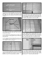
5. Prepare the hinge slots for the rudder as you did the
elevators. Join the rudder to the fin with the hinges and use
30-minute epoxy to simultaneously glue the tail gear wire in
the rudder and the tail gear bearing in the fuse. Do not glue
the nylon bearing to the rudder. Glue the hinges in
position with thin CA. NOTE: Petroleum jelly on the areas
where the tail gear bearing contacts the wire will ensure that
it does not glue to the tail gear wire or rudder.
❏
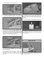
1. Install the engine and hook up the fuel lines and throttle
pushrod.
❏
2. Install a 1-1/4" tail wheel with a 3/32" wheel collar.
❏
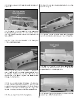
1. Reattach all control horns.
❏
2. With the model inverted in the stand and using the plan
as a reference, locate the pushrod tube exits on the model.
Trim the covering from these openings. Reinstall the
pushrods and hook up the control surfaces.
❏
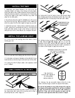
3. Wrap the receiver in 1/4" (or thicker) foam. Wrap the
battery in 1/4" foam. Temporarily position them as shown on
the plan. Note: You will use these components to help set
your C.G.
NOTE: The balance and control throws for the
SlowPoke have been extensively tested. We are
confident that they represent the settings at which the
SlowPoke flies best. Please set up your model to the
specifications listed above. If, after you become
comfortable with your SlowPoke, you would like to
adjust the throws to suit your tastes, that’s fine. Too
much throw can force the plane into a stall, so
remember, “more is not better.”
Do not confuse this procedure with “checking the C.G.”,
which will be the next step in balancing your model.
A model which is not laterally balanced properly may exhibit
a variety of unpleasant tendencies, such as uncharacteristic
tip stalls. This aircraft, when balanced properly, has NO
such bad tendencies. Be sure to check the lateral balance
carefully as described to help ensure that the model
exhibits the same handling qualities of our prototypes.
❏
1. With the wing level and attached to the model (and the
engine and muffler installed), lift the model by the propeller
shaft and the fin several times. Notice which wing tip drops.
Hint: You may need assistance to perform this step.
❏
2. The wing which consistently drops is the heavy side.
Balance the model by adding weight to the other tip.
Balance the Model Laterally
BALANCE YOUR MODEL
We recommend the following control surface throws:
NOTE: The throws are measured at the widest part of
the elevators and rudder. Adjust the position of the
pushrods at the control/servo horns to control the
amount of throw. You may also use the ATV’s if the
transmitter has them but the mechanical linkages should
still be set so the ATV’s are near 100% for maximum
servo power and the best servo resolution (smoothest,
most proportional movement). Be sure to confirm your
surfaces move the correct direction.
High Rate
Low Rate
ELEVATOR:
5/8" up
1/2" up
5/8" down
1/2" down
RUDDER:
2" left and right
NOTE: If the radio does not have dual rates, then set the
control surfaces to move between the high rate and low
rate throws.
CARBURETOR WIDE OPEN
RUDDER MOVES RIGHT
ELEVATOR MOVES UP
4-CHANNEL
TRANSMITTER
RADIO SETUP
TRANSMITTER
4-CHANNEL
TRANSMITTER
4-CHANNEL
Set the Control Throws
Final Servo & Receiver Installation
Install the Hardware
28
Summary of Contents for SlowPoke
Page 6: ...6 DIE CUT PATTERNS...
Page 32: ...TWO VIEW...

