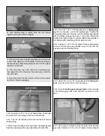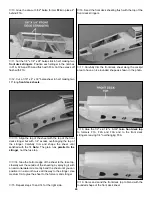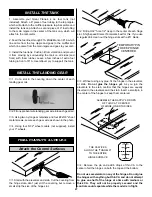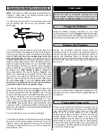
Reference this photo for the next 5 steps.
❏
10. Position the rudder servo in the left side of the servo
tray as shown on the plan. Mount the servo.
❏
11. Center the rudder and position the servo arm
perpendicular to the servo case. Mark the pushrod where it
crosses the servo arm. Bend the pushrod and connect it to
the servo arm with a Faslink
™
. Trim the excess wire that
protrudes past the Faslink. Unhook the clevis and
temporarily remove the rudder.
❏
12. Fit the elevators to the stabilizer, using hinges to hold
it in place. DO NOT GLUE the hinges in position at this time.
❏
13. Screw a clevis onto the elevator pushrod wire at least
14 turns. Slide the pushrod through the elevator pushrod
guide tube on the left side of the fuselage. Position and
temporarily mount the elevator control horn to the right
elevator as you did with the rudder control horn.
❏
14. Install the elevator servo as shown on the plan.
Position the servo arm square with the servo case and set
the elevators to neutral. Mark the pushrod where it crosses
the servo arm, bend it and connect it to the servo arm with
a Faslink. Trim the excess wire above the Faslink.
❏
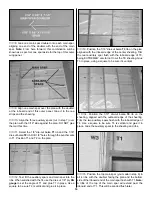
15. Mark the location of the tail gear wire on the rudder
and the nylon tail gear bearing on the fuselage.
❏
16. Remove the rudder and elevators from the model.
Using a pen, draw lines around the control horns and
remove the control horns. Poke approximately a dozen
holes in each surface’s control horn location with the tip of
a hobby knife, or T-pin. Remove the hinges from each
surface, then use thin CA to harden the wood inside the
lines you drew where the control horns attach.
❏
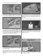
17. Drill a 7/64" hole 5/8" deep in the leading edge of the
rudder at the mark you made for the tail gear wire. Test fit
the tail gear wire in the rudder. Cut a slot in the trailing edge
of the fuse at the marks you made for the nylon tail gear
bearing. Without using any glue, test fit the rudder to the fin
with the tail gear wire. When satisfied with the fit, remove
and set it aside.
❏
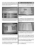
1. Remove all the pushrods and remove the hinges and
control horns from the elevators and rudder. Remove the
engine and any other hardware you may have installed.
❏
2. Most of the model should be rough-sanded by now,
with all the tabs and rough edges sanded even. Fill all
dents, seams, low spots and notches with HobbyLite
™
Balsa
Colored Filler.
❏
3. After the filler has dried, use progressively finer grades
of sandpaper to even all the edges and seams and smooth
all surfaces. Remove all balsa dust from the model with
compressed air or a vacuum with a brush followed by a
tack cloth.
Before you cover the fuselage, first apply 1/4" wide strips of
MonoKote film in the corners of the stab and fuse and the
fin and the fuse, then proceed to cover the fin and stab with
pre-cut pieces that meet in the corners and overlap the 1/4"
strips. Never cut the covering on the stab and fin after it
has been applied except around the leading and trailing
edges and at the tips. Modelers who cut covering on top of
the wood structure may cut through the covering and into
the stab or fin. This will weaken the structure to a point
where it may fail during flight.
After the model is covered, you must fuelproof the inside of
the front bottom sheeting and cockpit. You may do so with
fuelproof model paint, 30-minute epoxy thinned with
alcohol, or finishing resin.
1. Using the template on the plan as a guide, cut a
windshield from the supplied butyrate sheet.
2. Use canopy glue to adhere the windshield to the covering
in the position shown on the plan. Hint: A piece of pinstripe
tape along the contact area makes an attractive seam.
INSTALL THE WINDSHIELD
FUELPROOF THE MODEL
COVER THE MODEL WITH
MONOKOTE FILM
PREPARE FOR COVERING
2-56 (.074")
Pushrod Wire
Servo Horn
FasLink 1/16"
26
Summary of Contents for SlowPoke
Page 6: ...6 DIE CUT PATTERNS...
Page 32: ...TWO VIEW...

