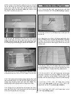
1. Assemble your Great Planes 4 oz. fuel tank (not
included). Attach a 6" piece of fuel tubing to the top nipple,
which will attach to the muffler pressure tap. Assemble and
install the tank cap. Attach a second piece of 6" fuel tubing
to the main nipple in the center of the tank cap, which will
attach to the carburetor.
2. Feed the fuel lines through F1A. Hint: Mark on F1A which
line came from the top nipple and goes to the muffler and
which line came from the main nipple and goes to your carb.
3. Install the fuel tank. Cushion it from vibration and prevent
it from moving by surrounding the tank on all sides (and
front) with foam rubber. Leave a few inches of extra fuel
tubing in front of F1A. Use leftover ply to support the tank.
❏
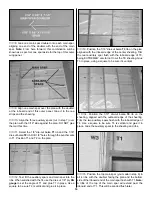
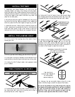
1. Cut a slot in the covering down the center of each
landing gear rail.
❏
2. Fit one prebent wire landing gear wire into each gear rail.
❏
3. Using two nylon gear retainers and four #2x3/8" sheet
metal screws, secure each gear wire as shown in the photo.
❏
4. Using four 5/32" wheel collars (not supplied), install
your 3" wheels.
❏
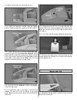
1. Start with the elevators and stab. Cut the covering from
the hinge slots–don’t just slit the covering but remove a
small strip the size of the hinge slot.
❏
2. Drill a 3/32" hole 1/2" deep in the center of each hinge
slot. A high speed Dremel Tool works best for this. If you use
a regular drill, clean out the hinge slots with a #11 blade.
❏
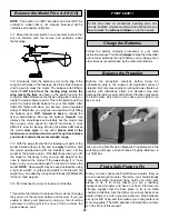
3. Without using any glue, fit the hinges in the elevators
or stab. Do not glue the hinges yet. As you join the
elevators to the stab, confirm that the hinges are equally
inserted in the elevators and the stab. Insert a small pin in
the center of the hinges to keep them centered.
❏
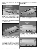
4. Remove the pin and add 6 drops of thin CA to the
center of all the hinges on both the top and the bottom.
Do not use accelerator on any of the hinges. Do not glue
the hinges with anything but thin CA and do not attempt
to glue one half of the hinge at a time with medium or
thick CA. They will not be properly secured and the
controls could separate while the model is in flight.
THE CA WICKS
ALONG THE "TUNNELS"
TO THE ENTIRE
HINGE SURFACE
ASSEMBLE, THEN APPLY 6 DROPS
OF THIN CA TO CENTER
OF HINGE, ON BOTH SIDES
TEMPORARY PIN
TO KEEP HINGE
CENTERED
Attach the Control Surfaces
FINAL HOOKUPS & CHECKS
INSTALL THE LANDING GEAR
INSTALL THE TANK
27
Summary of Contents for SlowPoke
Page 6: ...6 DIE CUT PATTERNS...
Page 32: ...TWO VIEW...

