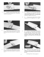
D 28. Spread a couple drops of thick CA on the battery
compartment doublers in the area of the servo rails and wing
hold-down plate. Use a piece of waxed paper to spread it
smooth.
ASSEMBLE FUSELAGE
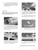
D 1. Trial fit the die-cut 1/8" ply formers F-3 and F-4.
You may have to sand the top comers slightly to make the
formers fit perfectly. (Remove only a very small amount at
a time).
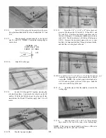
view, working on a flat surface and glue the Lt. fuse side to
F-3 and F-4. NOTE: The bottom edges of the fuse sides
must be down on the flat surface during this step.
D
4. Trial fity our e l e c t r i c motor through the hole in F-
2. Sand the hole as necessary for a snug fit (Use a piece of
sandpaper wrapped around a dowel). NOTE: If the motor
label gives you problems when fitting, you may want to peel
off the label.
D 5. Note that we have punched the locations of the two
screw holes in F-l. Drill 1/8" holes at these two locations.
Be sure to use a wood backing when drilling to prevent
damaging the part you are drilling.
D 6. Mount F-1 onto the front of the motor with the two
M3 x 6 metric screws.
D 2. Glue F-3 and F-4 to the Rt. fuse side. Use a square
to make sure these formers are installed at right angles
(perpendicular) to the fuse side.
M3x6 SCREW
D 3. Place the fuselage upright on the fuselage top
D 7. With F-1 mounted to the motor and F-2 positioned
9


