just protrudes into the inside of the fuse. Then mark the tube
on the outside (allowing 1/4" extra) and cut it off. Repeat for
the other side.
D 4. With the cable guide tubes in place, apply thin CA
where they enter the fuse.
D 5. Cut and sand the tubes off even with the surface of
the fuse top.
INSTALL SERVO RAILS
NOTE: The plans and photos show installation of Futaba S-33
servos. If you are using a different type servo you may have to
modify the servo rails and installation procedure.
D
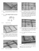
5. Cut a heavy paper shim and lay it on the fuse
bottom, under the servos (to prevent the servos from touch-
ing the bottom). With the servos and rails in place, glue the
rails to the fuse sides and F-4 with thin CA. Remove the
servos after the glue has hardened.
D
1. While you can still easily reach through F-4, place
a few drops of thick CA on the fuse bottom in the receiver
area and smooth it out with a piece of waxed paper. This
Strengthens the balsa in the area where the receiver will be
fastened with Velcro.
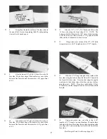
2. Stick two servos together with the square of
double-stick tape. NOTE: Make sure the servos are
positioned as shown on the plan.
D
D 6. Cut 1/4" balsa triangles to fit under the servo rails.
Glue in place. Add thick CA as necessary for secure glue
joints.
INSTALL WING PLATE
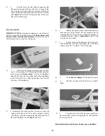
D 1. Find the 1/8" x 1/2" x 2-1/16" birch ply wing plate
and sand it as necessary to fit snugly between the fuse sides.
D 3. Install the servo grommets and eyelets, and mount
the servos to the die-cut 1/8" ply servo rails using the screws
provided with your radio.
D 4. Sand the servo rails a little at a time until the
servo/rail assembly fits snugly between the fuse sides at the
front of F-4.
D 2. Position the wing plate exactly as shown on the
plan and glue it in place.
D 3. Build up fillets of thick CA or epoxy all around the
wing plate, on top and bottom, to securely lock it in place.
NOTE: This installation must be very strong!
14


