background image

  ◎ Specifications

  ◎ Product description (Mechanical Parts)

  ◎ Specifications

1. HOPPING TELEMETRY TRANSMISSION (HoTT)
The use of up to 35 hopping channels provides advanced reliable 
operation while keeping from any external interference. 

2. Designed for beginners, X-4S HoTT Transmitter is the best choice 
for those who enjoy car, boat, and tank models. When optional 
Graupner/SJ Telemetry sensor or temperature sensor is used, you 
may check the real-time information such as model voltage, user 
programmable warnings. It is easy to check from your transmitter. 

3. Unlike other binding systems which are widely used, X-4S HoTT 
Transmitter supports the fast binding system which is operated by 
pressing a button.

6

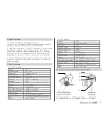
(1) X-4S Transmitter

(2) GR-4 Receiver

Channel
Operating Voltage
Battery Type
Operating Current
Operating Output Power
Frequency 
Modulation
Operating Temperature
Antenna
Display
Low voltage warning alarm
High temp warning alarm
Battery Charging
Firmware Update
Size
Weight

Channel
Frequency
Modulation
Operating Voltage
Operating Output Power
Operating Current
Display
Firmware update
Fail Safe
Temperature Sensor Warning
Low voltage warning alarm
Telemetry Sensor
Size
Weight

2CH 


4.8 ~ 6.0V  
Alkaline, Nixx 4 Cell 


app. 65mA   
App. 60 mW 


2.4000 ~ 2.4835 GHz   
FHSS 


app. -10 ~ +55`C ( app. -50 ~ +131℉ )
Dipole Antenna 


LED Indicator 


available (LED, Buzzer)  
DC Jack   
available (Futaba 3p connector) 


171.1 x 292.0 x 139.8 mm (6.74 x 11.49 x 5.50 in)
365.7g (12.89oz)

2 CH
2400~2483.5 MHz
FHSS
3.6~8.4V
60mW
35.0mA
One LED (red)
available (Port3)
Free/Fail safe
(T/V Connector) Port4 (50~150℃)
(T/V Connector) Port4 (1.0~25.5V)
(B/T Connector) Port3
30x21x14.3 mm (1.18x0.82x0.56 in)
app. 5.5g (0.19oz)

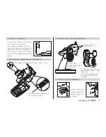
① Operating Panel     ② Steering Wheel      ③ Antenna
④ Communicating Port ⑤ Charging connector  ⑥ Trigger

Summary of Contents for X-4S HoTT SJ

Page 1: ...OPERATING INSTRUCTION Please read this manual thoroughly Keep this manual in a convenient place for quick and easy reference No 33400 www graupner com...

Page 2: ...rigger tension adjustment Steering wheel position adjustment Trigger Angle Adjustment Installation for left handed users Binding and Range test Control Switch Functions Fail Safe mode Configuration Tr...

Page 3: ...9 am to 5 pm PST Pacific Standard Time during the workweek Monday through Friday E mailed questions will be answered as soon as possible A S support During the warranty period we can repair this produ...

Page 4: ...operations of channels before use For the safe use please operate the Range Check Mode be fore use Be careful not to turn your transmitter off while in use Do not touch or grab antenna during the use...

Page 5: ...rating Current Operating Output Power Frequency Modulation Operating Temperature Antenna Display Low voltage warning alarm High temp warning alarm Battery Charging Firmware Update Size Weight Channel...

Page 6: ...vated please use new battery or recharge the used battery Please make sure the correct polarity when installing your battery Battery Charging If rechargeable battery is in use you can charge it up to...

Page 7: ...n your operating range 8 You may adjust trigger ten sion using driver You may adjust steering wheel tension using driver Steering wheel position adjustment Throttle Trigger Adjustment The angle could...

Page 8: ...our bolts and coverage Disconnect steering wheel part Disconnect transmitter connector Install your steering wheel part on your left side Then install the connector again then coverage and bolts Now y...

Page 9: ...is not controllable if your model is far away from you during Test mode due to the short transmit distance Control Switch Functions 1 REV Reverse Switch This is used to change the direction of the se...

Page 10: ...er beeps twice and it is re turned to Calibration Model Move steering and throttle to back and forward left and right then move to neutral position again Now your trans mitter beeps twice indicating C...

Page 11: ...4cycle 5cycle 6cycle Slow flash Low 2Time 90sec Low 3Time Low 2Time Port1 Port2 Port3 Port4 Function Ch1 Signal output Ch2 Signal output Telemetry Sensor Batt Temp Sensor Voltage Sensor HoTT v1 Senso...

Page 12: ...djustment and warning alarm function 3 Port 4 T V connector is designed that it will activate the beep and LED indicator when your engine gets hot Warning alarm would be activated if the batter is dis...

Page 13: ...Power switch Temperature sensor Connect temperature sensor to Engine head Steering Servo Receiver battery Throttle Servo Steering Servo T V Connector T V Connector B T Connector CH2 Connector CH1 Conn...

Page 14: ...able from 1 0V to 25 5V LiPo 4 cell max 25 2V In Auto selection Low voltage warning alarm is activated at 70 of detected voltage when power is on 5 ALARM EX TEMP Connect Temperature Sensor to Port 4 T...

Page 15: ...l interference in a residential installation This equipment generates uses and can radiate radio frequency energy and if not installed and used in accordance with the instructions may cause harmful in...

Page 16: ......

Reviews: