GRAUPNER GmbH & Co. KG D-73230 KIRCHHEIM/TECK GERMANY
Modifications reserved. No liability for printing errors. 06/2010
6
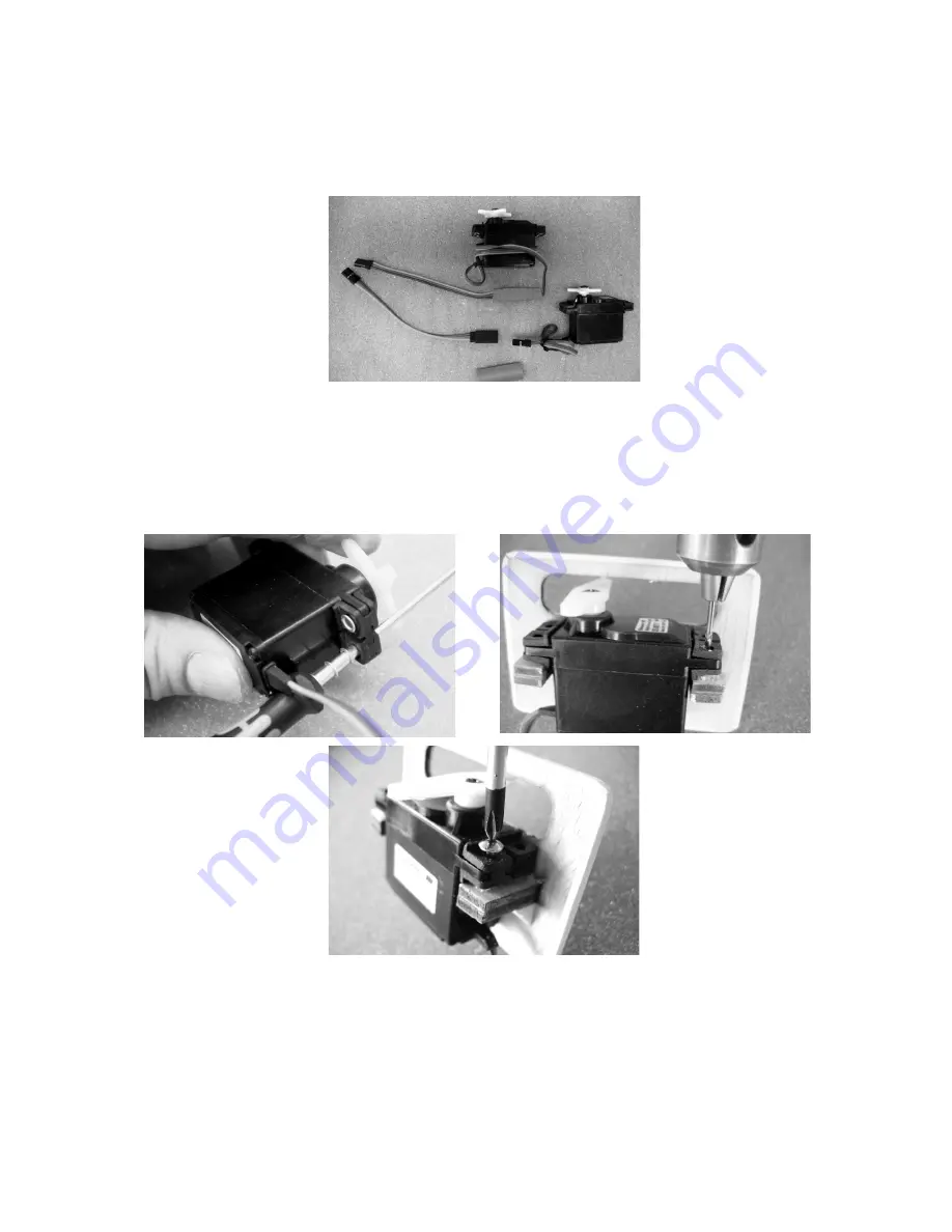
Lengthen the aileron servo leads with the appropriate extension leads, and fit a piece
of heat-shrink sleeve round each connection to prevent it working loose; a drop of
cyano also works well. Set the servos to centre from the transmitter, and fit the output
arms on the output shafts.
Set the servos to centre by connecting them to the receiving system. The wing-
mounted servos can now be attached to the support blocks using the retaining
screws supplied with them: the first step is to push the rubber grommets into the
servo mounting lugs, followed by the brass tubular spacers, with the flange on the
underside. The spacers are easier to fit if you slip them on a suitable screwdriver first.
Drill 1.5 mm Ø pilot-holes in the support blocks, using the metal spacers as a guide,
then fit the servo retaining screws as shown.
The servo leads can now be pulled through the wing panels using a length of thread:
tie the thread to the servo lead just behind the connector, then pull it through until it
appears at the root rib.
Run the servo leads out of both wing panels through the holes adjacent to the root
ribs, then temporarily fit cable ties on them to prevent them slipping back inside.


