16 / 33
Multirotor Installation
Verify that all propellers are removed from your multirotor.
Graupner
is not
responsible or liable for any injuries sustained during the installation and
setup of the mz-10C and GR-18C due to improper use or inattention to
safety procedures.
Find a proper location to mount the GR-18C receiver/controller, for
example, towards the front of the multirotor right behind the FPV camera
if you have one. Make sure that the ESCs and motors are properly
connected and that the four ESC wires are routed safely to a single spot
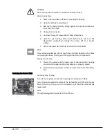
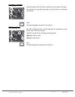
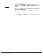
where the GR-18C location is going to be. Point the GR-18C antennas
towards the front of the multirotor and the connector ports towards the
back towards the ESC wires.
Wipe the surface of the multirotor with alcohol to assure proper adherence
before attaching the GR-18C. This step is critical to ensure that little to no
vibration will affect the flight performance of the GR-18C receiver. Secure
the GR-18C with the supplied 3M VHB double sided tape.
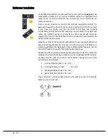
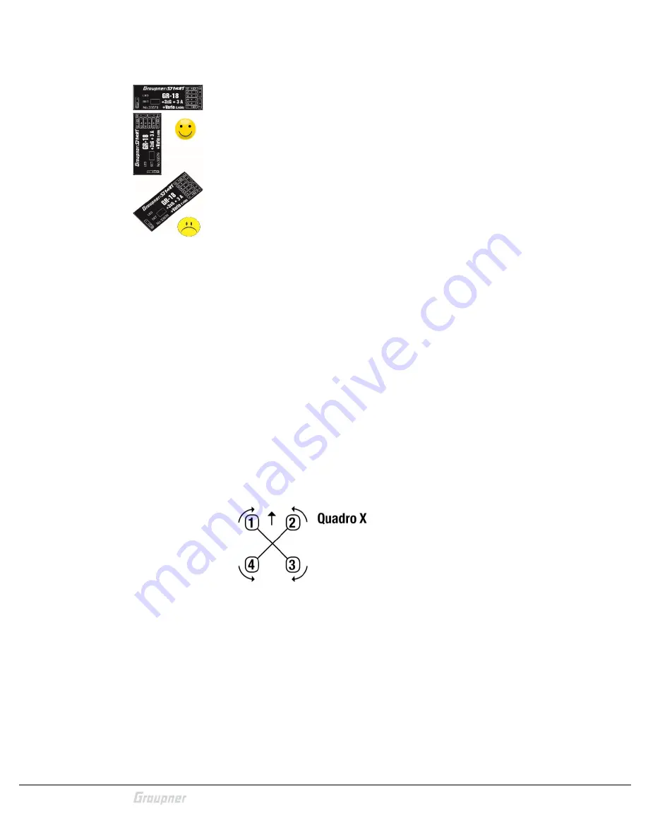
Number the ESC connections to assist with later setup. Check the motor for
markings that indicate clockwise (CW) or counter clockwise (CCW) rotation.
Number the ESCs with the back of the multirotor facing the user (front
points forward) as follows:
1.
Front Left Motor (CW) ch1 = Ch1
2.
Front Right Motor (CCW)
ch2 = Ch2
3.
Back Right Motor (CW) ch3 = Ch3
4.
Back Left Motor (CCW) ch4 = Ch4
Plug in the ESCs in order as determined in the previous step. For example,
Motor 1 goes to Ch1, etc.


