KayakDD-1 Digital Production Switcher
7.5.2
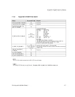
Supported GVG200 Commands
Name
Command Code
Remark
TRANSITION MODE COMMAND
CA
Only Write
TRANSITION RATE COMMAND
CC/CD
Only Write
TRANSITION PUSHBUTTON
SELECT COMMAND
FB
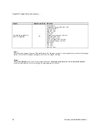
CROSSPOINT BUS COMMAND
C1-C4
(C1-CF for aux)
41-44
(41-4F for aux)
Crosspoint interpretation:
GVG code
Interpretation
01H...0x14
INPUT 1...20
15H
ME1 OUT
16H
ME2 OUT
17H
CLEAN FEED
18H
MAIN OUT
21H
ME3 OUT
25H...27H
COLOR BGD 1...3
30H...4BH
INPUT 21...48
Aux busses:
The number of Aux Busses in not limited.
If the effect address is 07H (= Aux Crosspoint) the lower nibble of the
command code will be interpreted as the AUX bus number.
So up to 15 Aux Busses can be controlled.
PUSHBUTTON COMMAND
C6
(C7 for REV,KEY CUT
keyer 1, KEY CUT
keyer 2)
Only MIX ,WIPE, REV and KEY CUT are supported.
MIX and WIPE will switch the currently selected buttons for next transition to
the given state.
WIPE PATTERN SELECT
COMMAND
C8
Only Write
ALL STOP COMMAND
F2
LEARN E-MEM REGISTER
DA
RECALL E-MEM REGISTER
DB
NOTE!
The GVG „DSK“ will always translated to the DD35 „PP“ mixer effect stage.
TIMING!
The standard GVG200 protocol timing will be used:
Commands will be executed in the third field after response
.
Planning and Installation Manual
87
Summary of Contents for KayakDD-1
Page 8: ...KayakDD 1 Digital Production Switcher Planning and Installation Manual 7 ...
Page 9: ...KayakDD 1 Digital Production Switcher 8 Planning and Installation Manual ...
Page 11: ...KayakDD 1 Digital Production Switcher 10 Planning and Installation Manual ...
Page 15: ...KayakDD 1 Digital Production Switcher 14 Planning and Installation Manual ...
Page 33: ...KayakDD 1 Digital Production Switcher 32 Planning and Installation Manual ...
Page 89: ...KayakDD 1 Digital Production Switcher 88 Planning and Installation Manual ...
Page 90: ...KayakDD 1 Digital Production Switcher Planning and Installation Manual 89 ...

