


SK200-UM-251-9370
9-17
9. ADJUSTMENTS USING THE SOFTWARE
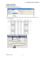
(5) (6): Y Offset
Sensors 1, 3, and 5 are attached 24.5 mm behind sensors 2 and 4 in the direction of the feed.
For this reason, there is always a 24.5 mm difference in the level of the scanned image.
Thus, 24.5 mm/0.0423 mm (1 pixel) = 579 (approx.) appears in these boxes.
In practice, values slightly greater or smaller than the above number will appear due to variations in sensor
position and feed.
Keep in mind that with larger values, sensor 1, 3 and 5 images will move farther up.
<<Handy Tip>> Basically, the physical positions of sensors remain unchanged, and sensors are mounted
with high accuracy. Therefore, if you find that a Y offset is significantly different from "579",
you may conclude that feed accuracy requires adjustment.
Conversely, if you know that the feed accuracy is correct, you may conclude that the sensor
physical position is incorrect.
You can use the correction value "579" to adjust the feed so that there is no misalignment in
the Y direction. This makes it possible to determine the feed, although this is not completely
accurate. You may use this technique for users who do not demand high accuracy.
(7) (9) (11): Starting Line
The distances (numbers of pixels) from the document sensor to each of the image sensors in the direction of
document feed are displayed in these boxes.
Subtracting value (9) from values (7) and (11) produces values (5) and (6), respectively.
If you change values (5) and (6) and press the "Check" button, values (9) and (11) will be calculated and
changed automatically.
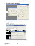
(8) (10) (12): Starting Bit
The image sensors themselves scan areas narrower than the area that can be physically scanned in order to
provide a correction range.
The numbers in these boxes represent the numbers of dots from the positions at which the sensors can start
their scan to those where the sensors actually start the scan.
Summary of Contents for SK200-09
Page 1: ...SK200 UM251 03 9370 SERVICE MANUAL MANUAL NO SK200 UM 251 ...
Page 6: ......
Page 10: ...SK200 UM 251 9370 1 4 1 OVERVIEW When the scanner is mounted on the high stand 1185 720 1100 ...
Page 38: ......
Page 40: ......
Page 42: ......
Page 100: ......
Page 112: ......
Page 135: ...SK200 UM 251 9370 13 23 13 BLOCK DIAGRAM AND CIRCUIT DIAGRAMS Power Board CN4091 07 2 4 ...
Page 136: ...SK200 UM 251 9370 13 24 13 BLOCK DIAGRAM AND CIRCUIT DIAGRAMS Power Board CN4091 07 3 4 ...
Page 137: ...SK200 UM 251 9370 13 25 13 BLOCK DIAGRAM AND CIRCUIT DIAGRAMS Power Board CN4091 07 4 4 ...
Page 162: ...SK200 UM 251 9370 13 50 13 BLOCK DIAGRAM AND CIRCUIT DIAGRAMS Power Board CN4091 17A 2 4 ...
Page 163: ...SK200 UM 251 9370 13 51 13 BLOCK DIAGRAM AND CIRCUIT DIAGRAMS Power Board CN4091 17A 3 4 ...
Page 164: ...SK200 UM 251 9370 13 52 13 BLOCK DIAGRAM AND CIRCUIT DIAGRAMS Power Board CN4091 17A 4 4 ...