


SK200-UM-251-9370
9-10
9. ADJUSTMENTS USING THE SOFTWARE
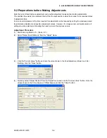
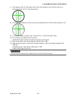
(7) Click anywhere within the "Theoretical" box and use the crosshairs cursor to click the white corner
indicated by arrow "C010" on the scanned image.
(8) Scroll the scanned image to click the white corner indicated by arrow "C090" with the crosshairs cursor.
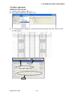
(9) The measured distance appears in the "Theoretical" box. Click the "Calculate" button.
(10) The correction value appears in the "Feed" box.
Click the "Set" button to allow the scanner to store the correction value.
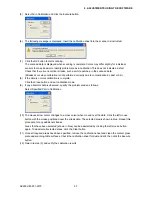
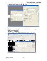
(11) Place the test chart on the scanner again and click the "Scan" button.
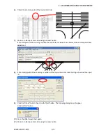
(12) Repeat Steps 4 through 9 to perform the following calculations, based on the figures displayed in the
dialog box.
[ (Theoretical value - Actual value) / Actual value ] x 100%
Confirm that this value is within ±0.1.
The scanner may be defective if the calculated values do not fall within the above ranges.
Summary of Contents for SK200-09
Page 1: ...SK200 UM251 03 9370 SERVICE MANUAL MANUAL NO SK200 UM 251 ...
Page 6: ......
Page 10: ...SK200 UM 251 9370 1 4 1 OVERVIEW When the scanner is mounted on the high stand 1185 720 1100 ...
Page 38: ......
Page 40: ......
Page 42: ......
Page 100: ......
Page 112: ......
Page 135: ...SK200 UM 251 9370 13 23 13 BLOCK DIAGRAM AND CIRCUIT DIAGRAMS Power Board CN4091 07 2 4 ...
Page 136: ...SK200 UM 251 9370 13 24 13 BLOCK DIAGRAM AND CIRCUIT DIAGRAMS Power Board CN4091 07 3 4 ...
Page 137: ...SK200 UM 251 9370 13 25 13 BLOCK DIAGRAM AND CIRCUIT DIAGRAMS Power Board CN4091 07 4 4 ...
Page 162: ...SK200 UM 251 9370 13 50 13 BLOCK DIAGRAM AND CIRCUIT DIAGRAMS Power Board CN4091 17A 2 4 ...
Page 163: ...SK200 UM 251 9370 13 51 13 BLOCK DIAGRAM AND CIRCUIT DIAGRAMS Power Board CN4091 17A 3 4 ...
Page 164: ...SK200 UM 251 9370 13 52 13 BLOCK DIAGRAM AND CIRCUIT DIAGRAMS Power Board CN4091 17A 4 4 ...