SK200-UM-251-9370
9-6
9. ADJUSTMENTS USING THE SOFTWARE
9.4 Making Adjustments
Always follow the sequence given below when making adjustments.
1. Calibration (white correction)
2. Feed distance adjustment
3. Position adjustment
Offset adjustment
Sensor joint alignment
4. Color correction
Scanner Calibration
Before beginning calibration, clean the contact glass plates and scanning-table surface. Any dust or dirt
on those surfaces may affect the calibration results and resulting image quality.
Check that the calibration sheet is free of any dust or dirt.
1. Calibration (white correction)
(1) Connect the scanner to the computer. Turn on the scanner, (connect the AC cable to the scanner power
inlet) then turn on the PC.
(2) Start Scanning Master 21+. (See p. 9-1.)
(3) Remove the white calibration sheet (220 x 1070 mm) from its special storage box.
Clean the conatct glass plate surfaces and the feed rollers.
220 mm
1070 mm
Calibration sheet
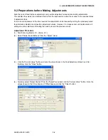
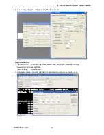
(4) Select "Calibration" from the "Adjust" menu.
Summary of Contents for SK200-09
Page 1: ...SK200 UM251 03 9370 SERVICE MANUAL MANUAL NO SK200 UM 251 ...
Page 6: ......
Page 10: ...SK200 UM 251 9370 1 4 1 OVERVIEW When the scanner is mounted on the high stand 1185 720 1100 ...
Page 38: ......
Page 40: ......
Page 42: ......
Page 100: ......
Page 112: ......
Page 135: ...SK200 UM 251 9370 13 23 13 BLOCK DIAGRAM AND CIRCUIT DIAGRAMS Power Board CN4091 07 2 4 ...
Page 136: ...SK200 UM 251 9370 13 24 13 BLOCK DIAGRAM AND CIRCUIT DIAGRAMS Power Board CN4091 07 3 4 ...
Page 137: ...SK200 UM 251 9370 13 25 13 BLOCK DIAGRAM AND CIRCUIT DIAGRAMS Power Board CN4091 07 4 4 ...
Page 162: ...SK200 UM 251 9370 13 50 13 BLOCK DIAGRAM AND CIRCUIT DIAGRAMS Power Board CN4091 17A 2 4 ...
Page 163: ...SK200 UM 251 9370 13 51 13 BLOCK DIAGRAM AND CIRCUIT DIAGRAMS Power Board CN4091 17A 3 4 ...
Page 164: ...SK200 UM 251 9370 13 52 13 BLOCK DIAGRAM AND CIRCUIT DIAGRAMS Power Board CN4091 17A 4 4 ...

