


SK200-UM-251-9370
8-23
8. DISASSEMBLING AND ADJUSTING THE MECHANICAL PARTS
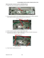
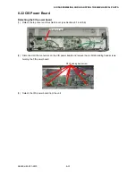
(12) Detach the bearings, collars and left side shaft link plates from the main unit.
(13) Lift up the rear part of the center media guide, slide it in the rear direction, and then detach the center
media guide from the main unit.
Center media guide
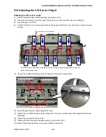
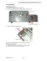
(14) Detach the four left and right side springs (AP100-024-0.9) the two front center springs (AP100-025-1.0),
and the two spring rear center springs (AP100-020-1.2) from the pressure arm.
Black spring
Front center pressure spring (AP100-025-1.0)
Left & right pressure spring (AP100-024-0.9)
Pressure arm
Rear center pressure spring (AP100-020-2.0)
Silver spring
Black spring
Summary of Contents for SK200-09
Page 1: ...SK200 UM251 03 9370 SERVICE MANUAL MANUAL NO SK200 UM 251 ...
Page 6: ......
Page 10: ...SK200 UM 251 9370 1 4 1 OVERVIEW When the scanner is mounted on the high stand 1185 720 1100 ...
Page 38: ......
Page 40: ......
Page 42: ......
Page 100: ......
Page 112: ......
Page 135: ...SK200 UM 251 9370 13 23 13 BLOCK DIAGRAM AND CIRCUIT DIAGRAMS Power Board CN4091 07 2 4 ...
Page 136: ...SK200 UM 251 9370 13 24 13 BLOCK DIAGRAM AND CIRCUIT DIAGRAMS Power Board CN4091 07 3 4 ...
Page 137: ...SK200 UM 251 9370 13 25 13 BLOCK DIAGRAM AND CIRCUIT DIAGRAMS Power Board CN4091 07 4 4 ...
Page 162: ...SK200 UM 251 9370 13 50 13 BLOCK DIAGRAM AND CIRCUIT DIAGRAMS Power Board CN4091 17A 2 4 ...
Page 163: ...SK200 UM 251 9370 13 51 13 BLOCK DIAGRAM AND CIRCUIT DIAGRAMS Power Board CN4091 17A 3 4 ...
Page 164: ...SK200 UM 251 9370 13 52 13 BLOCK DIAGRAM AND CIRCUIT DIAGRAMS Power Board CN4091 17A 4 4 ...