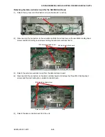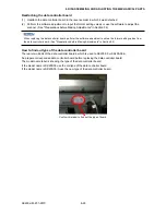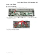
SK200-UM-251-9370
8-25
8. DISASSEMBLING AND ADJUSTING THE MECHANICAL PARTS
8.18 Adjusting the CIS Sensor Height
Adjusting the CIS sensor height
(1) Detach the board base chassis assembly (see Section 8.12).
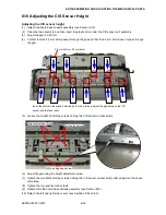
(2) Close the top assembly, and then insert the plastic shim under the CIS sensor unit assembly.
(3) Adjust the gap to 0.25 mm.
(4) Confirm that the 0.2 mm shim passes through the gap and that the 0.3 mm shim dose not pass through
the gap.
0.2 mm shim or 0.3 mm shim
Insert the shims in the areas indicated by the red circles to adjust the gap between the CIS
sensor and the feed roller.
(5) Loosen the two M3L4 binding screws holding the CIS sensor unit assembly.
M3L4 binding head screw
Height adjustment screw
Position lock screw
(6) Adjust the gap using the height adjustment screw.
(7) Tighten the two M3L4 binding screws holding the CIS sensor unit assembly after adjustment has been
completed.
(8) Tighten the two position lock screws.
(9) Reassemble the board base chassis assembly (see Section 8.12).
(10) Detach the left and right side covers (see Sections 8.2 and 8.3).
Summary of Contents for SK200-09
Page 1: ...SK200 UM251 03 9370 SERVICE MANUAL MANUAL NO SK200 UM 251 ...
Page 6: ......
Page 10: ...SK200 UM 251 9370 1 4 1 OVERVIEW When the scanner is mounted on the high stand 1185 720 1100 ...
Page 38: ......
Page 40: ......
Page 42: ......
Page 100: ......
Page 112: ......
Page 135: ...SK200 UM 251 9370 13 23 13 BLOCK DIAGRAM AND CIRCUIT DIAGRAMS Power Board CN4091 07 2 4 ...
Page 136: ...SK200 UM 251 9370 13 24 13 BLOCK DIAGRAM AND CIRCUIT DIAGRAMS Power Board CN4091 07 3 4 ...
Page 137: ...SK200 UM 251 9370 13 25 13 BLOCK DIAGRAM AND CIRCUIT DIAGRAMS Power Board CN4091 07 4 4 ...
Page 162: ...SK200 UM 251 9370 13 50 13 BLOCK DIAGRAM AND CIRCUIT DIAGRAMS Power Board CN4091 17A 2 4 ...
Page 163: ...SK200 UM 251 9370 13 51 13 BLOCK DIAGRAM AND CIRCUIT DIAGRAMS Power Board CN4091 17A 3 4 ...
Page 164: ...SK200 UM 251 9370 13 52 13 BLOCK DIAGRAM AND CIRCUIT DIAGRAMS Power Board CN4091 17A 4 4 ...


